MICRO
SEVEN MODEL AP45, PC-ALARM PANEL OR ALARM-PANEL SIMULATOR, dials preprogrammed
telephone number and sends preprogrammed contact-ID alarm messages via
telephone line after receiving trigger signals over RS232 interface or manual
switch. Or AP45 sends DC-09 type IP alarm message to IP server over Internet.
COPYRIGHTS MICRO SEVEN, INC. 2016
AP45
Contact-ID dialer
PC
connected via RS232 interface
ALARM CENTRAL STATION
OR MICRO SEVEN MODEL CT10
AP45
Contact-ID dialer
|
|
PC
connected via RS232 interface |
|
ALARM CENTRAL STATION
OR MICRO SEVEN MODEL CT10 |


Features:
-Contact-ID over telephone line and IP
-TCP
or UDP selectable
-IP proprietary DC09 server software included
-internal audio speaker
-Made in U.S.A.
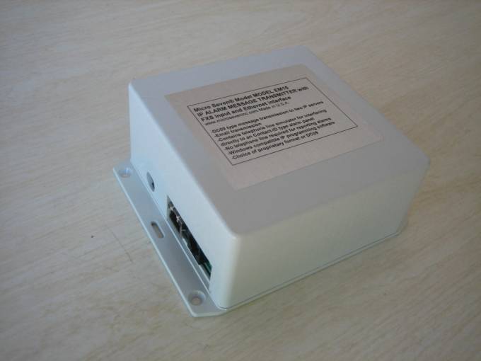
AP45 is shown in above picture with RS232 connector and
screw terminals in the rear section.
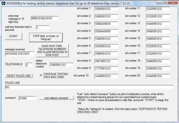
One of demo software is for testing central station
telephone lines as shown in the above picture. A test message is delivered to
alarm central stations by one of twenty lines. AP45 dials one of twenty
telephone numbers, delivers the test message, and checks reply messages. If it
receives “CALL FAILED”, telephone number is shown in “FAILED LINE” window.
Complete test results with real time data are stored in a disk file.
INTRODUCTION
Micro
Seven Model, PC-Alarm Panel or Alarm Panel Simulator, transmits Ademcoâ Contact-ID alarm
messages to alarm receivers by DC-level trigger signal at a screw terminal on
the box or starting commands sent at RS232C interface in PC. Alarm message and
dialing telephone number may be programmed and stored in non-volatile memory instead
of programming at each powering up the device.
DC-level trigger signal at a screw terminal starts dialing and
delivering Contact-ID messages to any central station receiver or Micro Seven’s
model CT10 or starting command at RS232 interface. After AP45 dials a telephone number for a receiver, the receiver
answers the call and transmits the handshake tones. Then AP45 transmits alarm
message in DTMF tone. If the receiver receives the alarm message correctly, the
receiver transmits kiss-off tone. Then AP45 hangs up the call at the telephone
line, and it sends output DC level signal to indicate that the process was
successful at a screw terminal and message success message at RS232 interface.
If the alarm reporting is not successful, AP45 transmits out DC level signal at
a different screw teriminal. Transmission of alarm messages is repeated for
four times if AP45 does not receive kiss-off tones. The whole sequence, which
involves re-dialing of telephone number, may be repeated for three times. There
is no sound-monitor nor speaker in AP45. A contact-ID alarm receiver/simulator
model CT10 is recommended for an alarm receiver.
SPECIFICATIONS
RS232C
interface: 151200 baud, no parity, and 8-bit character
Screw
terminal signals:
1. Telephone lines,
tip and ring (2 terminals)
2. DC power input (2
terminals, +12V and common)
3. Go/start input (1
terminal), negative active signal with a pull-up resistor to +5. An-open
collector transistor circuit or dry-contacts may be used.
4. Success output (1
terminal), positive polarity, 1: success, 0: no result or check with failure
signal, minimum 3.5 volt maximum 5.0 volt. The success output signal is cleared
when Go/Start signal is asserted.
5. Failure output (1
terminal), positive polarity, 1: success, 0: no result or check with failure
signal, minimum 3.5 volt maximum 5.0 volt, The failure output signal is cleared
when Go/Start signal is asserted.
RS232C commands from PC: Note: 200 ms delay
is required between programming commands including telephone number entry,
alarm message entry, and AP45 Control Register operations that involves with
non-volatile memory.
Telephone
number entry: D<telephone number-maximum fifteen digits><CR>
for example D5035551212<CR> for dialing 5035551212. Note <CR> is a carriage
return. It may be stored in EEROM (non-volatile memory) in AP45 depending on AP15
control register bit setting.
Alarm
message entry: S<fifteen digit long alarm message><CR>
i.e.
S123418313101015<CR>
Note: AP45 prepares check sums, so do not enter sixteen digits. When sixteen
digit-long alarm message including check sum is entered, checksum, which is
prepared by AP45. It may be stored in EEROM (non-volatile memory) in AP45
depending on AP15 control register bit setting
Start
alarm reporting: G
Start
alarm reporting process by dialing the telephone number, receive handshake
tones, transmit alarm messages, receive kiss-off tones and hang up the line if
AP15 Control Register is programmed.
Start
alarm reporting: J
Start
alarm reporting process by sending DC09 IP message to preprogrammed IP address
and Internet port number by using ipprog2.exe
Hang-up
command or Abort command: A
Turn off off-hook relay in AP45 or abort alarm reporting process.
Repeat
alarm message command: B
It
transmits alarm message again.
Reading
telephone-number command: T
AP45
transmits programmed telephone numbers to PC.
Reading
alarm-message command: U
AP45
transmits programmed alarm message in sixteen digit-long including check sum to
PC.
Status messages from AP45 to PC at RS232
interface
MESSAGE
SUCCESS
MESSAGE FAILED
CALL
FAILED
DC09 type packets transmitted by AP45:
(CRC codes) “ADM-CID”)
(event sequence number)(receiver number)(account pref.)(account number)(alarm
events, zone, partition)(MAC address)(time stamp)<CR>
Connectors:
Power switch and power connector for AC/DC power adapter
Telephone connector, RJ11C
Ethernet/Network connector
Power required: DC12V 200mA by AC/DC
power adapter
Dimensions: 5”x6”x2.5”
Weight: <500g (<1
LBS)
Environmental: Operating
temperature with power on: 0 to 35 degree C, Humidity: 85% RH at 35 degree C,
storage temperature and operating temperature without power on
Warranty
Service:
six months limited warranty. No warranty if any factory seal is broken.
Service
is performed at the factory, usually within 5 working days.
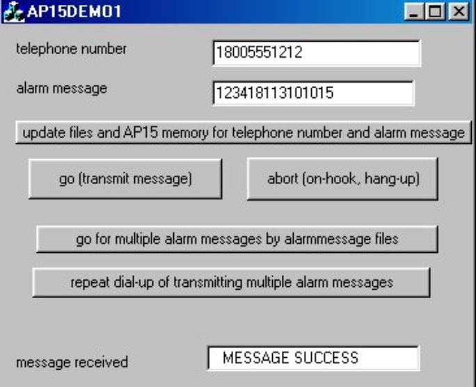
Software: A Windows-type demo software is included to
dial a telephone number and transmit alarm message. Multiple alarm messages may
be transmitted to alarm receivers in one call or continuous calls.
Another demo software is for testing central station
telephone lines as shown in the above picture. A test message is delivered to
alarm central stations by one of twenty lines. AP45 dials one of twenty
telephone numbers, delivers the test message, and checks reply messages. If it
receives “CALL FAILED”, telephone number is shown in “FAILED LINE” window.
Complete test results with real time data are stored in a disk file.
Programming
Software for AP45: Windows-type alarm message and telephone number programming
software is provided.
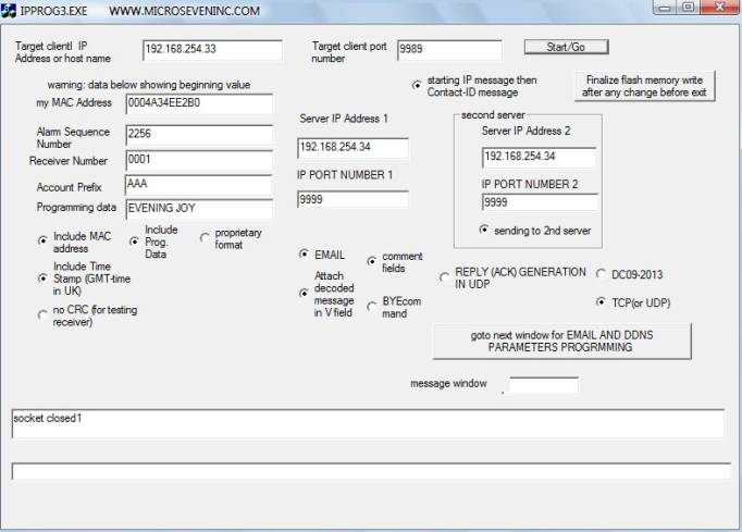
Detailed programming software for IP parameters
The screen shot of the programming
software is shown below. Programming of alarm sequence number, receiver number,
account prefix, programming data, server IP addresses, IP port numbers,
selections of adding MAC address and time stamp, Programming data field, email,
multi-line port(not shown) and other features is available. Selection between
TCP and UDP is available in a different screen.
Ipprog3.exe for
programming DC09 parameters, selection of TCP/UDP, history file output to PC
file, email parameters, V field programming and selection, P field programming
and selection, IP server/receiver selection, etc. The first screen shot is
shown below:
AP15 CONTROL REGISTERS
DTMF
Register
DTMF
Register in non-volatile memory determines on and off times of DTMF generation
of alarm messages.
Each
increment is 10 ms, and the factory default condition is 5 for 50ms on and off
timing. Ademco specification limits 50ms minimum and 60 ms maximum. The command
format is:
MA5 n1
n2
For example,
MA506 selects 60 ms on/off times.
The
content of DTMF Register may be done by "RA5", and AP45 outputs
"06".
Tone
detect register
Tone
detect register is threshold value for detecting handshake and kiss-off tones
for long-distance telephone calls.
Control
Register,
which resides in non-volatile memory, is one byte data memory in AP45. It is
written by the following command:
MAC n1
n2, where n1 n2 form one byte in hexadecimal notation
Note:
"MACB0" programs the factory default conditions.
Status
of the control register is performed by entering "RAC", and AP45
generates "50".
Bit 7:
"1" selects higher signal power output (0 dBm) for alarm message, and
"0" selects lower signal power output (-12 dBm). The factory default
is "0" to select –12dBm.
Bit 6:
"1" disables input signal amplification (x4) for detecting weak
handshake and kiss-off tones, and "0" enables input signal
amplification. The factory default is "1" for selecting normal input
signal .
Bit 5:
"1" disables storing telephone number in non-volatile memory for
telephone number input command, and "0" is for storing telephone
number in non-volatile memory. The factory default is "0" for
enabling non-volatile memory operation.
Bit 4:
"1" disables detection of busy tone, and "0" enables
detection of busy tone. Note; The busy-tone detection when enabled is between
time period for 2.5 seconds after the end of dialing. The factory is
"1" for disabling busy-tone detection.
Bit 3:
"1" selects rotary-pulse dialing, and "0" selects DTMF
dialing of telephone numbers. The factory default is "0" for DTMF
dialing.
Bit 2:
"1" disables re-dialing of telephone numbers when "MESSAGE
FAILED" is generated. "0" enables re-dialing of telephone number
for maximum times. The factory default is "0" for re-dialing
telephone numbers when "MESSAGE FAILED" is displayed.
Bit 1:
"1" keeps telephone line off-hook after successful delivery of alarm
messages. "0" enables hanging up the line after successful of alarm
messages. The factory default is "0" for hanging up the line.
Bit 0:
"1" disables re-dialing telephone numbers when message "CALL
FAILED" is displayed. "0" enables re-dialing telephone numbers.
The factory default is "0" for re-dialing telephone numbers.
Feature for AP45: WAB01 to turn audio monitor off and
WAB00 to turn audio monitor on (factory default).
EEROM for storing non-volatile memory is available
when the above AP15 control register bit 5 is clear.
Standards:
ANSI/SIA DC-09, 2007,
2013
DC-05 digital
communication standard (contact-ID)
IP server Windows program:
It is provided as a free
demo IP server Windows software program receiving proprietary DC09 IP
messages.
Option: international
AC/DC power adapter with four different power plugs (US, UK, Europe, and
Australia)
Micro Seven, Inc. ®
1095-K N.E. 25th Ave.
Hillsboro, OR
97124 U.S.A.
phone:
503-693-6982, fax: 503-693-9742