A
smaller MICRO SEVEN MODEL AP5, PC-ALARM PANEL OR ALARM-PANEL SIMULATOR, dials
preprogrammed telephone number and sends preprogrammed contact-ID alarm
messages via telephone line after receiving trigger signals over RS232
interface or manual switch.
COPYRIGHTS MICRO SEVEN, INC. 2016
AP5 Contact-ID
dialer
PC
connected via RS232 interface
ALARM CENTRAL STATION
OR MICRO SEVEN MODEL CT10
AP5 Contact-ID
dialer
|
|
PC
connected via RS232 interface |
|
ALARM CENTRAL STATION
OR MICRO SEVEN MODEL CT10 |

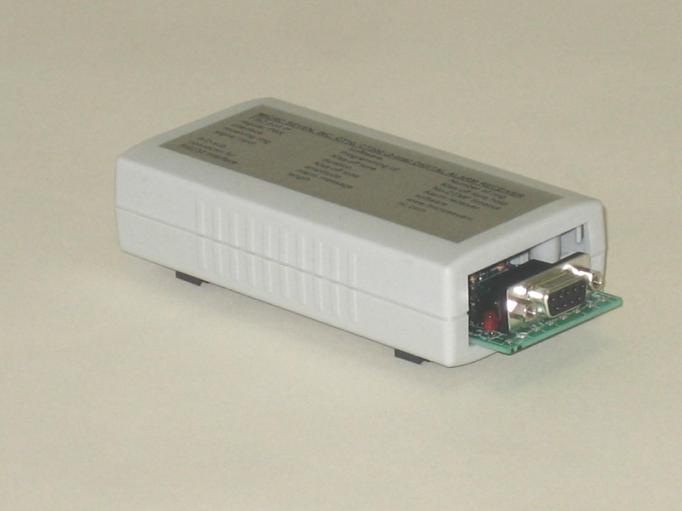
-Small, 3" x 1.5" x 4.5"
-Made in U.S.A.
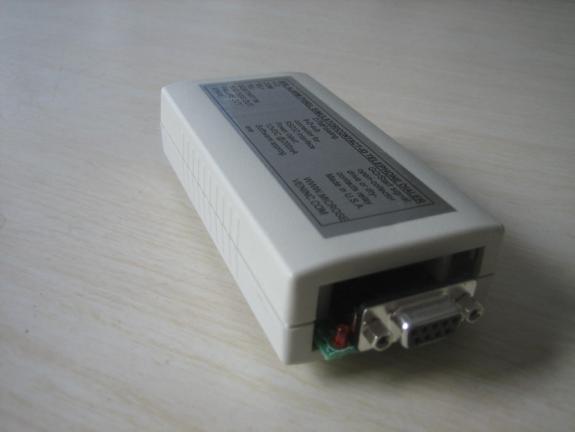
Front panel view of AP5 is shown in above picture.
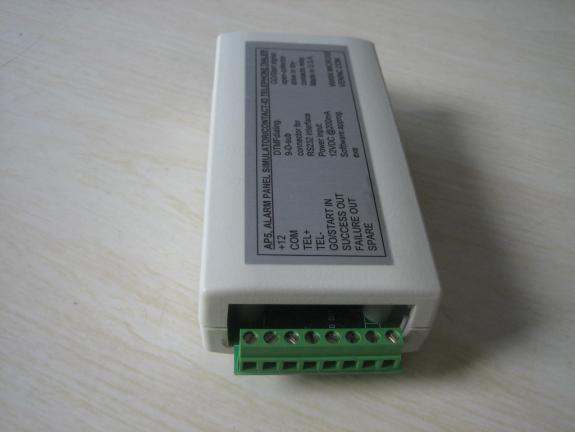
The rear view of AP5
is shown in the above picture.
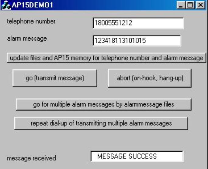
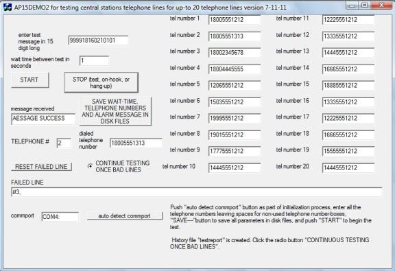
One of demo software is for testing central station
telephone lines as shown in the above picture. A test message is delivered to
alarm central stations by one of twenty lines. AP5 dials one of twenty telephone
numbers, delivers the test message, and checks reply messages. If it receives
“CALL FAILED”, telephone number is shown in “FAILED LINE” window. Complete test
results with real time data are stored in a disk file.
INTRODUCTION
Micro
Seven Model, PC-Alarm Panel or Alarm Panel Simulator, transmits Ademcoâ Contact-ID alarm
messages to alarm receivers by DC-level trigger signal at a screw terminal on
the box or starting commands sent at RS232C interface in PC. Alarm message and
dialing telephone number may be programmed and stored in non-volatile memory
instead of programming at each powering up the device. DC-level trigger signal at a screw terminal
starts dialing and delivering Contact-ID messages to any central station
receiver or Micro Seven’s model CT10 or starting command at RS232
interface. After AP5 dials a telephone
number for a receiver, the receiver answers the call and transmits the
handshake tones. Then AP5 transmits alarm message in DTMF tone. If the receiver
receives the alarm message correctly, the receiver transmits kiss-off tone.
Then AP5 hangs up the call at the telephone line, and it sends output DC level
signal to indicate that the process was successful at a screw terminal and
message success message at RS232 interface. If the alarm reporting is not
successful, AP5 transmits out DC level signal at a different screw teriminal.
Transmission of alarm messages is repeated for four times if AP5 does not
receive kiss-off tones. The whole sequence, which involves re-dialing of
telephone number, may be repeated for three times. There is no sound-monitor
nor speaker in AP5. A contact-ID alarm receiver/simulator model CT10 is
recommended for an alarm receiver. +12VDC power input
SPECIFICATIONS
RS232C
interface: 9600 baud, no parity, and 8-bit character, RTS/CTS hardware
handshake
Screw
terminal signals:
1. Telephone lines,
tip and ring (2 terminals)
2. DC power input (2
terminals, +12V and common)
3. Go/start input (1
terminal), negative active signal with a pull-up resistor to +5. An-open
collector transistor circuit or dry-contacts may be used.
4. Success output (1
terminal), positive polarity, 1: success, 0: no result or check with failure
signal, minimum 3.5 volt maximum 5.0 volt. The success output signal is cleared
when Go/Start signal is asserted.
5. Failure output (1
terminal), positive polarity, 1: success, 0: no result or check with failure
signal, minimum 3.5 volt maximum 5.0 volt, The failure output signal is cleared
when Go/Start signal is asserted.
RS232C commands from PC: Note: 200 ms delay
is required between programming commands including telephone number entry,
alarm message entry, and AP5 Control Register operations that involves with
non-volatile memory.
Telephone
number entry: D<telephone number-maximum fifteen digits><CR>
for example D5035551212<CR> for dialing 5035551212. Note <CR> is a
carriage return. It is stored in EEROM (non-volatile memory) in AP5.
Alarm
message entry: S<fifteen digit long alarm message><CR>
i.e.
S123418313101015<CR>
Note: AP5 prepares check sums, so do not enter sixteen digits. When sixteen
digit-long alarm message including check sum is entered, checksum, which is
prepared by AP5, will become a wrong one. It is stored in EEROM (non-volatile
memory) in AP5.
Start
alarm reporting: G
Start
alarm reporting process by dialing the telephone number, receive handshake
tones, transmit alarm messages, receive kiss-off tones and hang up the line if
AP15 Control Register is programmed.
Hang-up
command or Abort command: A
Turn off off-hook relay in AP5 or abort alarm reporting process.
Repeat
alarm message command: B
It
transmits alarm message again.
Reading
telephone-number command: T
AP5
transmits programmed telephone numbers to PC.
Reading
alarm-message command: U
AP5
transmits programmed alarm message in sixteen digit-long including check sum to
PC.
AP15 CONTROL REGISTERS
DTMF
Register
DTMF
Register in non-volatile memory determines on and off times of DTMF generation
of alarm messages.
Each
increment is 10 ms, and the factory default condition is 5 for 50ms on and off
timing. Ademco specification limits 50ms minimum and 60 ms maximum. The command
format is:
MA5 n1
n2
For
example, MA506 selects 60 ms on/off times.
The
content of DTMF Register may be done by "RA5", and AP5 outputs
"06".
Tone
detect register
Tone
detect register is threshold value for detecting handshake and kiss-off tones
for long-distance telephone calls.
Control
Register,
which resides in non-volatile memory, is one byte data memory in AP5. It is
written by the following command:
MAC n1
n2, where n1 n2 form one byte in hexadecimal notation
Note:
"MACB0" programs the factory default conditions.
Status
of the control register is performed by entering "RAC", and AP5
generates "50".
Bit 7:
"1" selects higher signal power output (0 dBm) for alarm message, and
"0" selects lower signal power output (-12 dBm). The factory default
is "0" to select –12dBm.
Bit 6:
"1" disables input signal amplification (x4) for detecting weak
handshake and kiss-off tones, and "0" enables input signal
amplification. The factory default is "1" for selecting normal input
signal .
Bit 5:
"1" disables storing telephone number in non-volatile memory for
telephone number input command, and "0" is for storing telephone
number in non-volatile memory. The factory default is "0" for
enabling non-volatile memory operation.
Bit 4:
"1" disables detection of busy tone, and "0" enables
detection of busy tone. Note; The busy-tone detection when enabled is between
time period for 2.5 seconds after the end of dialing. The factory is
"1" for disabling busy-tone detection.
Bit 3:
"1" selects rotary-pulse dialing, and "0" selects DTMF
dialing of telephone numbers. The factory default is "0" for DTMF
dialing.
Bit 2:
"1" disables re-dialing of telephone numbers when "MESSAGE
FAILED" is generated. "0" enables re-dialing of telephone number
for maximum times. The factory default is "0" for re-dialing
telephone numbers when "MESSAGE FAILED" is displayed.
Bit 1:
"1" keeps telephone line off-hook after successful delivery of alarm
messages. "0" enables hanging up the line after successful of alarm
messages. The factory default is "0" for hanging up the line.
Bit 0:
"1" disables re-dialing telephone numbers when message "CALL
FAILED" is displayed. "0" enables re-dialing telephone numbers.
The factory default is "0" for re-dialing telephone numbers.
EEROM for storing non-volatile memory is available
when the above AP15 control register bit 5 is clear.
Status messages from AP5 to PC at RS232
interface
MESSAGE
SUCCESS
MESSAGE FAILED
CALL
FAILED
Power
required: DC12V 200mA
Dimensions: 6 cm (2.5")
W x 3 cm (1.5") H x 14 cm (6") L
Weight: <500g (<1
LBS)
Environmental: Operating
temperature with power on: 0 to 35 degree C, Humidity: 85% RH at 35 degree C,
storage temperature and operating temperature without power on
Warranty
Service:
six months limited warranty. No warranty if any factory seal is broken.
Service
is performed at the factory, usually within 5 working days.
Software: A Windows-type demo software is included to
dial a telephone number and transmit alarm message. Multiple alarm messages may
be transmitted to alarm receivers in one call or continuous calls.
Another demo software is for testing central station
telephone lines as shown in the above picture. A test message is delivered to
alarm central stations by one of twenty lines. AP5 dials one of twenty
telephone numbers, delivers the test message, and checks reply messages. If it
receives “CALL FAILED”, telephone number is shown in “FAILED LINE” window.
Complete test results with real time data are stored in a disk file.
Programming
Software for AP5: Windows-type alarm message and telephone number programming
software is provided.
Micro Seven, Inc. ®
1095-K N.E. 25th Ave.
Hillsboro, OR
97124 U.S.A.
phone:
503-693-6982, fax: 503-693-9742
Micro Seven Inc.® model
CT10, CM10, and CT200 Low-cost alarm-receiver
Micro
Seven, Inc. model CT10, CM10, and CT200 for the Ademco® Alarm-Receiver
(registered trade mark by ADEMCO Group, a division of Pittway) with Contact ID
Protocol provides functions of generation of handshake tones and kiss-off
tones, receiving alarm messages, check-sum calculation, and transmitting alarm
messages in ASCII format at RS232C interface to a PC. Alarm receiver software
is provided.
CT10
or CM10 is shown in above picture.
Model LS15E+ with FXO and FXS interfaces is
strongly recommended instead of models CT10, CM10 and CT200 for setting up your
alarm system configuration.
Features
i Small, 3" x
1.5" x 4.5"
i Low-cost
i AC/DC Operation
i Low cost, and
portable
i Security Industry
Association’s Ademco® Contact ID Protocol
i Handshake and
kiss-off tones
i RS232C interface
to transmit alarm messages to PC and the control software to program
many parameters including telephone numbers
i Checksum
calculation of received alarm messages
i Caller-ID
receiver option (CT10)
i Car battery
adapter and 230 volt power options
i Alarm receiver
software
i Dialing and
relaying alarm messages to other alarm receiving as an optional feature
i 6 month warranty
Application
and benefit of alarm receiver
i Demonstration
and testing alarm control panels at factories and fields
i No alarm
receivers required for testing alarm control panels
i Complete testing
of alarm panels before the installation
i No PBX or local
telephone service needed for CM10
SPECIFICATIONS
CT10 and CT200: contains regular
telephone line interface.
CM10: simulated telephone line to
interface alarm panel with a piece of telephone cord.
CT200: dual line for receiving
simultaneous alarm messages at both lines.
DTMF
detecting signal power for alarm messages: -23dBm to +5dBm per a frequency with
maximum 4dB difference between frequencies
Alarm
message DTMF signal on time (Burst ON time): 50 ms minimum
Alarm
message DTMF signal off time (Burst OFF time): 50 ms minimum 400 ms maximum
Note:
Contact ID protocol requires Burst ON and OFF times to be 50 ms minimum and 60
ms maximum.
Handshake tones:
1400:
1400+/- 1Hz, duration of 100 ms +/- 1.5 ms, silence period of 100 ms +/- 1.5
ms, and
2300Hz:
2300+/-2 Hz duration of 100 ms +/- 1.5 ms
Kiss-off tones:
1400
+/- 1 Hz with duration of 750 ms
Line
Input Jacks: USOC-RJ11-C, standard modular phone jack
Characteristics
for CT10 and CT200:
High voltage
isolation: 1500VRMS between lines and RS232C connector.
Ring
signal detector: opto-coupler
Signal
isolation: telephone coupling transformer
Off-hook impedance: 50 ohms typical
High
ON-hook impedance is obtained by off-hook mechanical relay.
Handshake
tone is produced after 1.8 seconds when the off-hook relay is turned on.
Characteristics
for CM10:
Battery-feed
voltage and loop current: 24 volt and 25 mA
Programmable
inputting telephone number
Dial
tone and ring-back tone
Disconnect
signal
All
other signals required for alarm receivers.
RS232C Interface:
Speed: 1200 baud, with one stop bit, no parity bit
The
interface signals: Receive Data, Transmit Data, Data Set Ready, Clear-to-send,
and ground. The Data Terminal Ready signal is forced high at LS15E+ meaning
that a PC is always ready to receive data from LS15E+.
Connector: 9-pin D-sub on LS15E+ the rear panel
Cable(9-pin
M/9-pin F) is provided.
Received
alarm messages are computed for the checksum.
AC/DC
Adapter(provided with LS15E+): 117VAC +/- 5%, or 230VAC +/- 5%(for optional
230V AC/DC Adapter)
AC/DC
Adapter or Car Battery Adapter input: 12VDC unregulated, 800mA maximum
Line
Status Display: red LED for each line to indicate off-hook status (continuous
on)
Calibration:
not required because digitally synthesized tones
Power-On
Indicator: green LED display
Dimensions:
19 cm (4") W x 4.5 cm (1.75") H x 10 cm (7.5") L
Weight:
400g (0.8 LBS.)
Environmental:
Operating temperature: 0 to 35 degree C, Humidity: 85% RH at 35 degree C
Warranty/Service:
6 months limited warranty. No warranty if any factory seal is broken. Service
is performed at the factory, usually within 5 working days.
Options and Accessories:
Ethernet interface similar to model LS15ETH to transmit DC-09 IP messages to servers
Car
Battery Adapter
230V
input AC/DC Adapter (117V input unit is a standard.)
USB/RS232 adapter cable (virtual RS232 port at PC)
Reference: Digital Communication Standard-SIA DC-05-1999.09, Ademco Contact ID Protocol for Alarm System Communications
Alarm receiving software:
Standard alarm receiver software, that is provided at no charge, “as is” with no support, no liability, and no support from Micro Seven, in Windows operating system that receives and decodes caller-ID information and Contact ID alarm messages displays caller’s telephone number, name, date, nature of alarm messages on PC screen. The software also stores the same information as a text file. Any additional software requirement is custom.
We provide no
liability using all our products for alarm receiving and alarm receiving software to all people and companies including
alarm panel users, alarm central station, telephone companies, and all
distributors.
As an optional feature, dialing telephone numbers and delivering
Contact-ID messages to other alarm receivers is available.
Other
alarm products:
- LS15E, LS15E+, Micro Seven, Inc. Alarm
Receiver Simulator
- AP15, PC alarm
panel, RS232 compatible alarm panel
- PM10, Alarm panel
with excessive sound detection and low/high temperature monitor
- LS15ETH with
Ethernet interface
Micro Seven, Inc. ®
1095-K N.E. 25th Hillsboro, OR 97124 U.S.A.
PHONE: 503-693-6982, FAX: 503-693-9742
Home Page: www.microseveninc.com
Email: sales@microseveninc.com
Other
alarm receivers and related products
Typical connections
of CT10 and CM10 with alarm panels and PC are shown below.