Micro Seven, Inc.
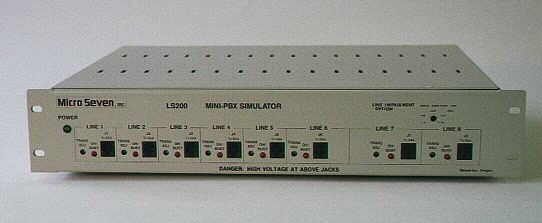
CALLER-ID TEST UNIT, model LS200-8G
Caller-ID Test Unit, model LS200-8G is equipped with a complete 8-line telephone line and caller-ID simulator that produces caller-ID signals under various central station and transmission line conditions.
Caller-ID Test Unit, model LS200-8G
Features
- 8-line telephone-line simulator with dual frequency call progress tones, ring signal, standard battery feed (loop voltage),and DTMF and rotary-pulse dialing method.
- On-hook and off-hook (with call-waiting) caller-ID in both single and multiple message formats.
- Distinctive ringing features.
- RS232C-programming of caller-ID FSK frequency components and amplitudes.
- RS232C-programming of random noise amplitude level that is mixed into Caller-ID Signals.
- RS232C-programming of line impairment circuit with envelope delay distortion and frequency attenuation characteristics for caller-ID FSK signals.
- RS232C-programming of telephone numbers, ring signal frequency & amplitude, and complete caller-ID parameters including names, privacy status, out-of-area status, visual waiting message, and call-waiting signals.
- RS232C-programming of call-waiting signals (SAS and CAS) for their frequencies and amplitudes.
Benefits
- Design verification of caller-ID receivers under the worst telephone line conditions.
- Quality and quantity test of caller-ID receivers under various signal levels, noise levels, frequency components, frequency attenuation, and envelope delay distortion.
- Format compatibility checks without using actual telephone lines.
- Ring signal compatibility checks for international application.
Application
- Testing of caller-ID receivers with or without call-waiting for engineering and manufacturing.
Micro Seven's Caller-ID Tester, model LS200-8G, is a complete telephone line simulators that includes ring signal, dual frequency call progress tones, and 40V battery feed. And it also provides caller-ID signals for on-hook and off-hook caller-ID (for call-waiting functions). It also provides RS232C programming of frequency and amplitude of caller-ID FSK signals, CAS and SAS signals for call-waiting caller-ID, random noise levels, and frequency and amplitude of ring signal. By changing frequencies and amplitudes of Caller-ID and call-waiting signals, caller-ID receivers may be tested under various test conditions with LS200-8G. The frequencies of the caller-ID FSK and call-waiting signals are precisely maintained for their accuracy. The random noise may be mixed to all the caller-ID and call-waiting Signals.
The amplitude level of the random noise is programmable also. Model LS200-8G provides independent amplitude controls for on-hook and off-hook FSK-signal generations. A disk containing application programs is conveniently provided for programming frequencies and amplitude of all signals.
Frequency attenuation and envelope delay distortion characteristics for caller-ID (FSK) signals may also be programmed by RS232C interface. Thus, caller-ID receivers are tested with LS200-8G for many different conditions such as signal level, noise content, frequency components, frequency attenuation characteristics, and envelope delay distortion.
Specifications
Ring Signal:
Range of Programmable Amplitude: 40 to 90 VRMS.
Range of Frequency: 16 to 68 Hz +/- 1 Hz, sine wave.
Maximum load: 5.5 k ohm (equivalent to 1.45 B of FCC Ringer Equivalent Number).
Call Progress Tones:
Power: -20 dBm nominal.
Dial tone: 350 Hz + 440 Hz, continuous.
Ring Back Tone: 440 Hz + 480 Hz, 2 sec ON/4 sec OFF.
Busy Tone: 480 Hz + 620 Hz, 0.5 sec ON/0.5 sec OFF.
Phone Number:(same as caller-ID directory number)
1 to 17 digits long for each line, and they may be programmable via dialing or RS232C interface.
DTMF Dialing:
Power input requirement is -13 dBm to +5 dBm per a frequency, and no more than 4 dBm difference between frequencies. All four line may dial simultaneously in DTMF mode with Multi-Line DTMF Dialer installed.
Pulse Dialing:
Break period: 45 to 75 ms (60 ms nominal)
Make period: 30 to 60 ms (40 ms nominal)
Line characteristics:(audio signals between connected lines)
Input impedance at 1 kHz: 600 ohms +/- 5%.
Signal Range: -45 to +5 dBm
Signal Bandwidth: 150 Hz to 5 kHz.
Front Panel Indicators:
Power and OH/BUSY indicators on the front panel.
Transmit Power Adjustment of Audio Signals:
(insertion loss control)
A potentiometer for each line, which is accessible through a front-panel hole, provides a control range of -2 to -42 dB.
Rear Panel Controls: power switch, fuse holder, power receptacle and RS232C connector
Mechanical Dimensions: 19 inch rack-mount unit with a dimension of 19"W x 3.5"H x 13"L
Weight: 12 lbs.
Power Requirements: 117 VAC RMS +/- 5%, 50/60 Hz, 30 watts maximum
Fuse: 0.3A, 3 AG, SLO-BLO
Environmental:
Operating temperature: 0 to 45 degree C
Humidity: 85% RH at 45 degree C
Warrant/Service:
6 months days limited warranty.
Service is performed at the factory within 10 working days.
Battery Feed Voltage (loop voltage): -45 V nominal
Caller-ID Features in LS200-8G
The Caller-ID feature for LS200-8G provides testing and demonstration of various caller-ID displays or receivers without obtaining caller-ID services from public telephone companies. The caller-ID information which consists of date, time, directory number (or privacy status or out-of-area status), name (optional), and call qualifier (long distance indication-optional) is transmitted only once during the silent period after the first ringing cycle. Programming of telephone number, or privacy status or out-of-area status for each line is programmable by dialing a special code or via RS232C interface. Complete programming of caller-ID parameters is accomplished by RS232C interface. The LS200-8G provides common telephone numbers for dialing and caller-ID generation purposes. A one to seventeen digit-long telephone number may be assigned to each line. The Caller-ID test, which may be started by RS232C command or DTMF dialing, generates eight different caller-ID data as each one is originated from one of eight lines.
Call Waiting Features in LS200-8G
The Caller-ID on Call Waiting Option for Micro Seven model LS200-8G, simulates caller-ID on call waiting feature from telephone company. In caller-ID on call-waiting, data is transmitted during off-hook condition. The called party automatically receives caller's information by FSK data transmission, so he or she knows how important the waiting call is. If he or she decides to answer the call, simply flash on-hook switch to put the current call on holding. Or When he or she hangs up the telephone set, ring signal is produced to alert for an incoming call. When the call is answered, two way voice paths are established between called line and call-waiting line. The call which was placed on holding may be connected again by pushing the flash button. It can go back and forth to switch between callers. The Caller-ID on Call Waiting data transmission from LS100 does not require channel seizure signal, and it also have a shorter mark period before FSK data.
The Subscriber Alert Signal (SAS), 440HZ sine wave signal, is generated to alert called line that a call is waiting. The SAS tone is produced always no matter caller-ID data is successfully transmitted or not by LS200. The SAS tone is continuously generated every 10 seconds. The duration of SAS tone, which is 300 ms as a power-up default condition, may be programmable by a RS232C command.
The CPE Alert Signal (CAS) consists of 2130 and 2750 Hz sine waves, and it is to signal CPE (customer provided equipment) that CID data is available. The duration of CAS tone, which is 80 ms as a power-up default condition, may be programmable by a RS232C command.
After LS200-8G generates SAS and CAS tones, it waits for CPE to transmit a DTMF tone for a maximum period of 160 ms. The DTMF tone must not be generated before the end of CAS tone. And also, the DTMF tone must be turned off before the acknowledgement timeout expires. The acknowledgement timeout is 160 ms in Bellcore documentation, but a shorter timer like 100 ms may be programmed to test a receiver. Programming of the timeout period may be done by a RS232C command.
The SAS tone with or without CAS is repeated in an interval set by the Call Waiting Reminder Timer, which is set as 10 seconds by a power-up default condition. It may be programmable by a RS232C command.
Reference of caller-ID on call-waiting: Bellcore TR-NWT-000030, Issue 2, October 1992 Voice-band Data Transmission Interface Generic Requirements
Frequency and Amplitude Programming in LS200-8G
Programming of caller-ID FSK signals, CAS and SAS signals for call-waiting caller-ID, random noise levels, and ring signals are provided. Frequencies and amplitude levels of caller-ID FSK signals (on-hook and off-hook caller-ID), CAS, SAS, and ring signals are done by a RS232C interface inside LS200. By changing frequencies and amplitudes of various signals in the caller-ID simulation, engineering testing of caller-ID receivers under various test conditions are possible with LS200-8G. The frequencies for the above signals are digitally controlled for their accuracy. The random noise that are mixed to all the signals except ring signal may provide testing of caller-ID receivers under the worst-case receiving conditions. The amplitude level of the random noise is programmable also. Model LS200-8G provides two separate signal paths for on-hook and off-hook FSK generations to provide accurate off-hook FSK signals. A disk containing application programs is conveniently provided for programming frequencies and amplitude of all signals. Battery protection of short-term power-loss is provided for frequency and amplitude programmed data. Line Impairment circuit that provides frequency attenuation characteristics and envelope delay distortion may be included to generate highly distorted caller-ID signals.
Frequency Programming of FSK Signal via RS232C Interface
1200Hz component: Range between 1180 and 1220 Hz with +/- 2 Hz
2200Hz component: Range between 2150 and 2250 Hz with +/- 2 Hz
Frequency Programming of CAS Signal, 2750Hz component:
Range between 2675 and 2825 Hz
with accuracy of +/- 2 Hz
Frequency Programming of CAS Signal, 2130Hz component:
Range between 2085 and 2175 Hz
with +/- 2 Hz
Frequency Programming of SAS Signal, 440Hz component:
Range between 430 and 450 Hz
with +/- 1 Hz
Amplitude Programming of the following signals are provided:
SAS signal (440Hz): -8 to -28 dBm into 604 ohms
2130 Hz component in CAS: -8 to -28 dBm into 604 ohms
2750 Hz component in CAS: -8 to -28 dBm into 604 ohms
FSK signal (1200, 2200Hz) in off-hook transmission: -8 to -28 dBm into 604 ohms
Random noise level in SAS, CAS, FSK signal in off-hook transmission: (1200 and 2200 Hz): 0.054 VRMS (-23 dBm) maximum: -23 to -43 dBm into 604 ohms
FSK signals in on-hook (1200 and 2200 Hz): 0.900 V RMS maximum and 0.090 V RMS minimum into open circuit. 0.148 V RMS maximum and 0.015 V RMS minimum into 900 ohms
Random Noise Level in On-hook FSK: 0.146 V RMS maximum and 0.015 V RMS minimum into open circuit, .070 V RMS maximum and 0.007 V RMS minimum into 900 ohms
Line Impairment Circuit in LS200-8G
One of different circuit conditions may be selected by a RS232C command for caller-ID FSK signals.
Mode 1: The full line-impairment mode contains the frequency attenuation characteristics and full envelope delay distortion.
Mode 2: The partial line-impairment mode contains the frequency attenuation characteristics and partial envelope delay distortion.
Mode 3: This mode contains the frequency attenuation characteristics but no envelope delay distortion.
Mode 4: This mode contains no frequency attenuation characteristics and no envelope delay distortion, and this is considered as a best condition.
Frequency Attenuation Characteristics
+12 dB +/- 1.5 dB @ 300 Hz.
+ 8 dB +/- 2.0 dB @ 500 Hz.
+ 8 dB +/- 1.5 dB @ 2500 Hz.
+12 dB +/- 1.5 dB @ 3000 Hz.
Above Band (>3000 Hz): 80 dB/octave roll-off to 50 dB holding to 10 kHz.
Below Band (<300 Hz): 24 dB/octave roll-off.
Full Envelope Delay Distortion Relative to 1700 Hz:
800-2600 Hz: 1750 micro sec nominal.
300-3000 Hz: 3000 micro sec nominal at both band edges.
Partial Envelope Delay Distortion Relative to 1700 Hz:
800-2600 Hz: 1250 micro sec nominal.
300-3000 Hz: 3000 micro sec nominal at both band edges.
Micro Seven, Inc.
U.S.A.