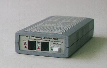
MICRO SEVEN, INC.® model
LS15-E1
Alarm receiver/telephone line simulator
for connecting Contact-ID alarm panel directly
with attenuating signal input and adding random noise
for simulating bad telephone line
conditions
and for analyzing received alarm signal timing and amplitude
Preliminary information
with subject to change
Copyrights Micro Seven, Inc.®, 2016
LS15E1
contains one simulated telephone line/FXS port for interfacing Contact-ID alarm
panel. LS15E1 provides all necessary electrical signals for alarm panel
including detecting dial tone, dialing telephone numbers, providing handshake
signal and kiss-off tone. LS15E1 receives Contact-ID signals from alarm panels,
and transmits ASCII equivalent characters of the received signal to PC via
RS232 interface. A demo central station software displays decoded alarm
messages. Bi-directional signal paths between LS15E1 and alarm panel may be
attenuated for 20dB by provided Windows based control software. Random noise
may also be injected to bi-directional signals with its amplitude adjusted also
by the control software. Trigger signal for loop is located at Line 2
connector.
Features
of Alarm-Receiver Simulator portion of LS15-E1
Features:
- Small, 4" x 1.75" x
7.5"
- Generation of handshake and kiss-off tones
- RS232C interface to transmit alarm messages to PC and the alarm receiver
software provided
- Contact-ID alarm-receiver simulator
- Dialed number display at PC accepting any telephone number
- Received DTMF signal amplitude data and timing output at PC
- Handshake signal frequency programmable and also amplitude programmable
- Kiss-off tone frequency programmable and also amplitude programmable
- Random noise with amplitude programmable inserted both signal directions
between alarm panel and LS15E1
- Duration of handshake tone for each frequency component is programmable.
- Programmable delay between alarm signal received and generation of kiss-off
tone
- Trigger signal of loop open/close for alarm panels is included.
- Holding kiss-off tone generation
SPECIFICATIONS
Telephone number receiving: any telephone number with
dialed number display output using the control software
DTMF dialing signal
power: -13dBm to +5dBm per a frequency with maximum 4dB difference between
frequencies.
Pulse dialing: Break
period: 45 to 75 ms (60 ms nominal), make period: 30 to 60 ms (40 ms nominal)
DTMF detecting signal
power for Contact-ID alarm messages: -23dBm to +5dBm per a frequency with
maximum 4dB difference between frequencies as a factory standard, the DTMF
detection threshold programmable by the control software
Alarm message DTMF
signal on time (Burst ON time): 50 ms minimum
Alarm message DTMF
signal off time (Burst OFF time): 50 ms minimum 400 ms maximum
Note: Contact ID
protocol requires Burst ON and OFF times to be 50 ms minimum and 60 ms maximum.
Detailed DTMF on/off timing received alarm panels are
displayed in the PC screen i.e. 50 for 50ms 99 for over 99ms
Received
DTMF signal amplitude data is displayed on screen.
Handshake tones:
As a factory standard:
1400: 1400+/-
1Hz, duration of 100 ms +/- 1.5 ms, silence period of 100 ms +/- 1.5 ms, and
2300Hz: 2300+/-2 Hz
duration of 100 ms +/- 1.5 ms
Frequencies of
handshake signal are programmable for +/- 20% using the control software. Also
duration of handshake tone is programmable.
Kiss-off tones: 1400 +/- 1 Hz with duration of 750 ms as a
factory standard. The duration of kiss-off tone is programmable between 10ms and 2.5seconds.
Frequency is programmable for +/- 20% using the control
software.
Programmable delay time in second between received good
Contact-ID messages and generation of kiss-off tone. The range is between 0 and
10 seconds.
Kiss-off generation hold off feature is available using the
control software.
Kiss-off and
handshake tones amplitude: selectable among -14 dBm, -20 dBm, and -30 dBm by
control software as a factory standard
Programmable-between –6 dBm and –40 by the control
software
Bi-directional signal paths: insertion
losses are 0 or 20 dB. Random noise is
added to each signal path for –10 dBm and –60 dBm.
Line impairment condition may be selected among the following three different
simulated telephone line:
1.
simulating ideal telephone circuits
2. 20 dB insertion loss
3. 20 dB insertion loss and random noise injection
Battery-feed
voltage (loop voltage): -20 volts
Off-hook impedance
requirement: 400 ohms maximum DC, 600 ohms nominal AC
Call Progress Tones:
single frequency or dual frequency type selected by control software
The duration of
disconnect signal is programmable.
Stutter dial tone:
selected by control software
Dry-contact output is at line 2 jack for center pins for tripping
alarm loop via software control and RS232. The output is selectable Normally
Open or Normally Closed.
Front panel control:
Power switch
Power indicator
Line 1: RJ11 connector for alarm panel input (FXS)
Line 2: dry-contact for loop input.
Line Status Display:
red LED to indicate off-hook status
Rear panel control: RS232 connector, power connector
RS232C
Interface:
Speed: 1200 baud, with one stop bit, no parity bit
The interface
signals: Receive Data, Transmit Data, Data Set Ready, Clear-to-send, and
ground. The Data Terminal Ready signal is forced high at LS15F meaning that a
PC is always ready to receive data from LS15F.
Connector: 9-pin D-sub on LS15F the rear panel
Cable(9-pin M/9-pin
F) is provided.
Received alarm
messages are computed for the checksum.
AC/DC Adapter: 117VAC
+/- 5%, or 230VAC +/- 5%(for optional international AC/DC power adapter)
AC/DC Adapter or Car
Battery Adapter input: 12VDC unregulated, 800mA maximum
Calibration: not
required because digitally synthesized tones
Power-On Indicator:
green LED display
Dimensions: 19 cm
(4") W x 4.5 cm (1.75") H x 10 cm (7.5") L
Weight: 400g (0.8 LBS.)
Environmental:
Operating temperature: 0 to 35 degree C, Humidity: 85% RH at 35 degree C
Warranty/Service: 6
months limited warranty. No warranty if any factory seal is broken. Service is
performed at the factory, usually within 5 working days.
Option:
International AC/DC
Adapter (117V input unit is a standard.)
Reference: Digital Communication Standard-SIA
DC-05-1999.09, Ademco Contact ID Protocol for Alarm System Communications
Software provided: control software and central station demo
software
Made in United States of America
Micro Seven, Inc. ®
1095-K N.E. 25th Hillsboro, OR 97124 U.S.A.
phone: 503-693-6982, fax: 503-693-9742
Home Page: www.microseveninc.com
Email: sales@microseveninc.com