MICRO SEVEN MODEL AP100, PC-ALARM PANEL OR ALARM-PANEL
SIMULATOR, contains four dialers for Contact-ID, SIA-FORMAT, and pulse 4X2 FOR
SENDING ALARM MESSAGES from PC with RS232 interface.
Copyright 2023 Micro Seven, Inc.
INTRODUCTION
Micro
Seven Model AP100, PC-Alarm Panel or Alarm-Panel Simulator, transmits
Contact-ID, Pulse 4X2 or SIA-FORMAT alarm messages to alarm receivers by
starting commands sent at RS232C interface in PC. PC sends ASCII alarm message
for Contact-ID and Pulse 4X2 or Hexadecimal messages to AP100. PC also sends
telephone number to AP100. Since the alarm messages, telephone numbers, and
AP100 Control Register for storing programming parameters are stored in non-volatile
memory in AP100, so single ASCII command at RS232C interface starts alarm
reporting process. After AP100 dials a telephone number for a receiver, the
receiver answers the call and transmits the handshake tones. Depending on which
protocol mode that is selected, AP100 transmits one of three protocol messages
to alarm receiver. AP100 sends status messages back to PC. If the alarm
reporting is not successful, AP100 transmits a different status message to PC.
Transmission of alarm messages is repeated for four times if AP100 does not
receive positive acknowledge tone. The whole sequence, which involves
re-dialing of telephone number, may be repeated for three times. AP100 contains
audio monitor internally to hear dialing process, handshake signals, alarm signal
transmission, and acknowledge tone/kiss-off tone. Internal EEROM provides
auto-dialer function with provided 104 port auto dialer software.
SPECIFICATIONS
RS232C
interface: 115200 baud, no parity,
and 8-bit character, no handshakes
DTMF
tone frequencies:
Transmitting DTMF tone
frequencies at AP100 are accurate within -0.027% of the specifications. And
their transmitting DTMF tones amplitude is selected for high or low power
output level (see AP100control register below for programming transmission level).
The measured DTMF frequencies
for the factory default values are as follows while the standard values are in
parenthesis:
696 Hz (697Hz), 769Hz (770Hz), 851Hz
(851Hz), 941Hz (941Hz), 1212Hz (1209Hz), 1334Hz (1336Hz), 1481Hz (1477Hz), and
1633Hz (1633Hz)
Programming and real-time operations
without auto-dialer:
Line
Selection Open Command: L +(line number, 1-4)
Note:
Line Open Command opens dedicated communication between PC and one dialer in
AP100 for programming auto-dialer or sending commands to only one line.
Line
Selection Close Command: #####
Note:
Line Selection Close Command closes dedicated communication between PC and
selected dialer. Commands are transmitted to all lines at once. For example,
##### and G starts dialing and sending messages at all four lines.
Telephone number entry: D<telephone number-maximum fifteen
digits><CR>
for example D5035551212<CR> for dialing 5035551212. Note <CR> is a
carriage return.
Warning: each telephone number digit must be 0, 1, 2, 3, 4, 5, 6, 7, 8,
9, *, #, or , (comma). Note: comma adds two seconds
delay between digits.
Alarm message entry for Contact-ID or Pulse 4X2:
S( in maximum 15 ASCII characters for Contact-ID or 6
ASCII characters for Pulse 4X2)<CR> for Contact-ID or Pulse 4X2
Note: AP100 prepares checksum at the end of string for Contact-ID.
Warning: ASCII character for Contact-ID must be 0, 1, 2, 3, 4, 5, 6, 7, 8, 9, B, C, D, E, or F. All other character may result in failed transmissions. Please note that ‘A’ is an illegal character for Contact-ID alarm message.
Warning: ASCII character for Pulse 4+2 must be 0, 1, 2, 3, 4, 5, 6, 7, 8, 9. All other character may result in failed transmissions.
Alarm
message entry for SIA-FORMAT:
Because alarm message for SIA-FORMAT contains binary number, input requires
hexadecimal number. It is memory write command for storing memory address 0D0H
or 0xD0. The memory address is 0D0h, 0D1H, 0D2H, 0D3H, 0D4H------. The end of
message is indicated by 0FFH.
For example, sending an address block data of 46 23 30 30 30 31 31 31 31 requires the following:
KD046KD123KD230KD330KD430KD531KD631KD731.
Note: The column parity byte is automatically prepared and attached at the end
of message by AP100.
New entry format is also
available to enter hexadecimal notation with ‘S’ header as follows:
S(hexadecimal two character ASCII)
(hexadecimal two character ASCII)-----.
For example, sending an address block data of 46 23 30 30 30 31 31 31 31 requires the
following:
S0623303030313131<CR>
Note: The column-parity byte is automatically prepared and attached at the end
of message by AP100.
Protocol selection:
W7F00 for selecting
Contact-ID, W7F01 for selecting SIA-FORMAT, or W7F02 for selecting Pulse 4X2.
Start
alarm reporting: G
Start alarm reporting process by dialing the telephone number,
receive handshake tones, transmit data blocks, and receive kiss-off tones.
Hang-up
command or Abort command: A
Turn off off-hook relay or abort alarm-reporting process.
Repeat
alarm message command: B
It transmits alarm message again. Transmitting alarm messages must
be programmed prior to sending this repeat alarm message command.
Reading
telephone-number command: T
AP20 transmits programmed telephone numbers to PC.
Reading
alarm-message command: U
AP20 transmits programmed data block to PC in hexadecimal
notation.
Continuous
message transmission mode without turning off telephone relay:
Instead of transmitting single message, multiple messages are transmitted by
sending “WACB2”.
Single
message transmission mode:
WACB0
Multiple
message transmission mode:
WACB2
Status
messages when the status message is enabled using the demo software.
The bit 5 of AP100control register 3
(EEROM address AB) is on, the following status message is output.
S00 Turning on telephone relay
S01 Begin to dial
S02 Receiving the Contact-ID handshake signal
S05 Transmission of Contact-ID message
S0A Hanging up the telephone line by turning off
the telephone relay
The bit 7 of the control register is
on, no audio on the speaker is produced.
Writing and reading
data memory:
W(hexadecimal notation of
address)(hexadecimal notation of byte), i.e. W2001 for writing 01 at data
memory address hex 20.
R(hexadecimal notation of address), i.e. R55 for outputting 01
Note: on power-up, data memory at
addresses A0-AF is loaded by data in the same addresses of EEROM.
Writing and reading EEROM:
M(hexadecimal
notation of address)(hexadecimal notation of byte), i.e. M2001 for writing 01
at EEROM address hex 20.Confirmation of “C” is received.
Q(hexadecimal notation of address), i.e. Q55 for outputting 01
AP100 CONTROL REGISTERS
AP70ControlRegister (both
EEROM and data memory address AB): note: the factory default condition is all
bits with zeros.
Bit 7:
Disable Audio at speaker when it is on. Factory default condition is off for
enabling the audio speaker.
Bit 6: Enable Debug Messages, which replaces regular messages with special
debug messages, with factory default condition for disabled.
Bit 5: Replace regular messages with messages with “M”, with factory default
condition for disabled.
Bit 0: Auto-dialer with factory default condition for disabled.
DTMF Register
DTMF
Register in non-volatile memory determines on and off times of DTMF generation
of alarm messages.
Each
increment is 10 ms, and the factory default condition is 5 for 50ms on and off
timing. Ademco specification limits 50ms minimum and 60 ms maximum. The command
format is:
MA5
n1 n2
For
example, MA506 selects 60 ms on/off times.
The
content of DTMF Register may be done by "RA5", and AP100 returns
"06".
Tone detect
register
Tone
detect register is threshold value for detecting
handshake and kiss-off tones for long-distance telephone calls.
Control Register,
which resides in non-volatile memory, is one byte data memory. It is written by
the following command:
MAC
n1 n2, where n1 n2 form one byte in hexadecimal notation
Note:
"MACB0" programs the factory default conditions.
Status
of the control register is performed by entering "RAC", and AP100
returns "50".
Bit
7: "1" selects higher signal power output (0 dBm) for alarm message,
and "0" selects lower signal power output (-12 dBm). The factory
default is "0" to select –12dBm.
Bit
6: "1" disables input signal amplification (x4) for detecting weak
handshake and kiss-off tones, and "0" enables input signal
amplification. The factory default is "0".
Bit
5: "1" disables storing telephone number in non-volatile memory for
telephone number input command, and "0" is for storing telephone
number in non-volatile memory. The factory default is "0" for
enabling non-volatile memory operation.
Bit
4: "1" disables detection of busy tone, and "0" enables
detection of busy tone. Note; The busy-tone detection when enabled is between
time period for 2.5 seconds after the end of dialing. The factory is
"1" for disabling busy-tone detection.
Bit
3: "1" selects rotary-pulse dialing, and "0" selects DTMF
dialing of telephone numbers. The factory default is "0" for DTMF
dialing.
Bit
2: "1" disables re-dialing of telephone numbers when "MESSAGE
FAILED" is generated. "0" enables re-dialing of telephone number
for maximum times. The factory default is "0" for re-dialing
telephone numbers when "MESSAGE FAILED" is displayed.
Bit
1: "1" keeps telephone line off-hook after successful delivery of
alarm messages. "0" enables hanging up the line after successful of
alarm messages. The factory default is "0" for hanging up the line.
Bit
0: "1" disables re-dialing telephone numbers when message "CALL
FAILED" is displayed. "0" enables re-dialing telephone numbers.
The factory default is "0" for re-dialing telephone numbers.
Handshake
tone detection: 1400/2300Hz for Contact-ID, 1400Hz for
Pulse 4X2, or 2225Hz for SIA-FORMAT
SIA-FOPMAT
mode:
Signal
transmission of data block for SIA-FORMAT: 300 baud or 110 baud selectable
Parity bit (9th bit): enabled/disabled
Wrong column parity: enabled/disabled
Acknowledge tone detection: 2025Hz for positive acknowledgement and 2225Hz for negative
acknowledgement.
Messages
received from AP100:
MESSAGE
SUCCESS
MESSAGE FAILED
CALL FAILED
Note:
<CR> is a hex 0D.
J+(1-4)
<space>(“T” +time stamp)
<space>(“P”+One-digit Protocol)<space>(“#” +Dialed telephone
number)<space> (“M”+(Alarm Messages in ASCII)<space>>”MESSAGE
SUCCESS”<CR>
Note:
Because SIA-FSK format contains binary data, hexadecimal noted data is
transmitted for alarm messages.
Auto-Dialer Operation:
Auto-dialer
operation is started or stopped with the AP100 programming software, AP100Program.exe.
Once started the auto-dialer, PC is not required for auto-dialer except emails
are not transmitted notifying “CALL FAILED” messages.
Message
example of auto-dialer operation:
L000
J4 T00002A #234567890 P0 M123456789012345 MESSAGE SUCCESS
J4
T0000FC #234567890 P0 M234567890123456 MESSAGE SUCCESS
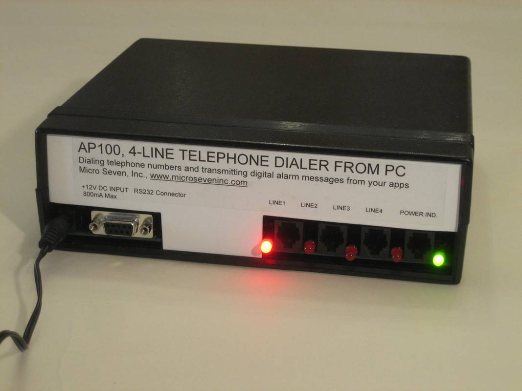
Front and rear panels:
Power
switch
Power
indicator
DC
power input, DC12V, 200 mA
RS232C
interface connector, 9-pin D-sub, female
Four
RJ11 connectors
Line
indicators (four)
AC/DC
Adapter
Dimensions: 19
cm (4") W x 4.5 cm (1.75") H x 10 cm (7.5") L
Weight:
750g (1.65 LBS)
Environmental:
Operating temperature with power on: 0 to 35 degree C, Humidity: 85% RH at 35
degree C, storage temperature and operating temperature without power on
Warranty
period: six months
The
screen for demo program, AP100DEMO1.EXE, for Contact-ID mode is shown below:
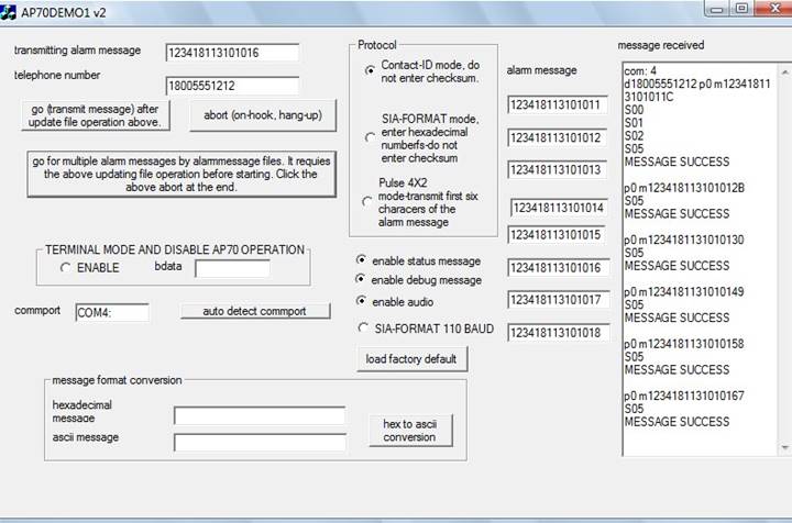
Here is an
example of demo1:
#####
(clear any PC to any line connection)
L4
(Selecting line 4)
WAC32
(setting the Control Register for the multiple message transmission mode)
W7F00
(selecting Contact-ID mode)
D092
(Dialing 092)
S123456789012345
(Contact-ID message, note that only fifteen-digit entry after ‘S’, and carriage
return (0dh))
G
(Go for dialing the telephone number and sending the Contact ID message)
Transmitted
data from AP100:
J4
T00060C #092 P0 M123456789012345 MESSAGE SUCCESS
Note:
There is a carriage return character with hex 0D at the end of the message:
J4:
fourth jack in AP100
T00060C: time stamp value, five-digit hexadecimal number incrementing each
second
#092 : dialed telephone number
P0: contact-ID protocol
M123456789012345: Contact-ID message
MESSAGE SUCCESS
Second
message:
S234567890123456
(next Contact-ID message to be transmitted)
B
(Transmit the Contact-ID message, ‘B’ is equivalent for ‘G’ without dialing )
L4
(Reply from AP100 indicating line 4)
MESSAGE
SUCCESS
(Reply from AP100)
T092 P0 M234567890123456
(Reply from AP100 and dialed telephone number and transmitted message)
S345678901212345
(next Contact-ID message to be transmitted)
B
(Transmit the Contact-ID message, ‘B’ is equivalent for ‘G’ without dialing )
L4
(Reply
from AP100 indicating line 4)
MESSAGE
SUCCESS
(Reply
from AP100)
T092 P0 M345678901212345
(Reply from AP100 and dialed telephone number and transmitted message)
A
(Hang-up the telephone line and end the process)
Auto dialer programming software for AP100
dialer option is shown below. Multiple messages are transmitted in one call.
Protocol mode, telephone number and alarm messages are downloaded into AP100
for auto-dialing mode, which does not require PC for it. The dialer option
provides programming of up to 104 lines. The second window display programs
line programming among lines 24 and 52. Third window and fourth window programs
lines 53-81 and 82 to 104 lines respectively. The AP100 dialer software
produces history files with real-time data inside PC. The AP100 dialer runs
independently from the AP100 dialer software.
IP Option for AP100:
The auto-dialer results are sent to two IP Receivers
via Internet. In case of CALL FAILED, email is also transmitted. Consecutive
emails for CALL FAILED are disabled until MESSAGE SUCCESS is received.
The
first screen is for port 9999. The second screen is for port 9998. All received
messages are stored in a file in your PC.

Other applications of AP100/Auto-dialer:
Alarm Central Station Tester with four
AP100s dialing over two thousand telephone numbers and sending all alarm messages
for testing telephone lines and alarm receivers at central stations.
Block diagram of CP100 system, where PC
for programming telephone number, alarm protocol, and alarm messages. Internet
is for receiving error reports and see progress reports:
Micro Seven, Inc.
Portland, OR
97229