MICRO
SEVEN MODEL AP15-4, PC-ALARM PANEL OR ALARM-PANEL SIMULATOR
It
dials telephone number and sends contact-ID alarm messages via telephone line
after receiving trigger signals over RS232 interface or manual switch. Typical application
is in Nurse-Call systems sending alarm messages to central station receiver
from PC software. Model
AP70 is available for Contact-ID, Pulse 4+2 and SIA-FSK #1 with auto dialing
mode also.
COPYRIGHTS MICRO SEVEN, INC. 2015, 2016, 2020, 2024, 2025
In the above example, patient’s room
number may also be included in Contact-ID alarm messages so that paramedics can
proceed to the room as soon as possible.
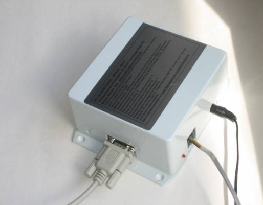
Model AP15 is shown below:
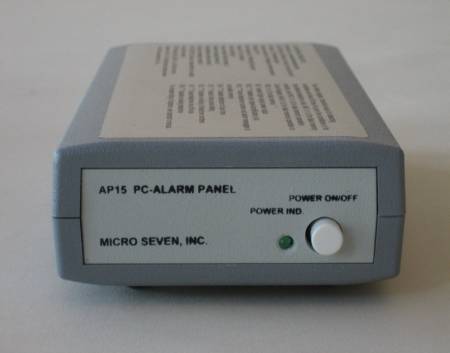
Front panel view of
AP15 is shown in above picture.
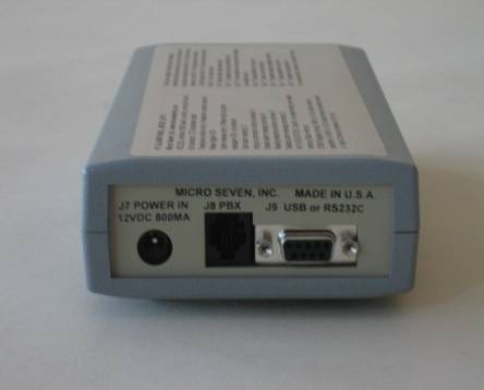
Rear panel view of AP15 is shown in above picture.
The demo software, AP15DEMO3 is for testing central station
telephone lines as shown in the above picture. A test message may be delivered
to alarm central stations by one of twenty lines. AP15 dials one of twenty
telephone numbers, delivers the test message, and checks reply messages. If it
receives “CALL FAILED”, telephone number is shown in “FAILED LINE” window.
Complete test results with real time data are stored in a disk file. Email
generation using AP15Demo3 software for reporting failed lines and also for
good results.
INTRODUCTION
Micro
Seven Model AP15, PC-Alarm Panel or Alarm Panel Simulator, transmits Ademcoâ Contact-ID alarm
messages to alarm receivers by starting commands sent at RS232C interface in
PC. PC sends ASCII equivalent of alarm message to AP15 without check-sum. PC
also sends telephone number to AP15. Since the alarm messages, telephone
numbers, and AP15 Control Register for storing programming parameters are
stored in non-volatile memory in AP15, so a single ASCII command at RS232C
interface start alarm reporting process. After AP15 dials a telephone number
for a receiver, the receiver answers the call and transmits the handshake
tones. Then AP15 transmits alarm message in DTMF tone. If the receiver receives
the alarm message correctly, it transmits kiss-off tone. Then AP15 hangs up the
call, and it sends status messages to PC. If the alarm reporting is not successful,
AP15 transmits a different status message to PC. Transmission of alarm messages
is repeated for four times if AP15 does not receive kiss-off tones. The whole
sequence, which involves re-dialing of telephone number, may be repeated for
three times. AP15 contains audio monitor internally to hear dialing process,
handshake signals, DTMF tones for alarm messages, and kiss-off tones. AC/DC
adapter and interfacing cable between PC and AP15 is provided. 220V AC/DC
adapter is optional. A contact-ID alarm receiver/simulator model CT10 is
recommended for an alarm receiver.
SPECIFICATIONS
Model AP15-4 contains new firmware for
making compatible with older model AP15-2, which were used for Tektone
Nurse-Call System. Model AP15-4 contains firmware change for removing extra
character after the MESSAGE SUCCESS before message terminating character, hex
0d, or carriage return.
Kiss-off
tone receiving window after transmission of Contact-ID messages: 6.6 second
maximum for extra time needed for cellular communication
Transmitting DTMF tones, Measured Value
(Standard Value) in both high and low power output levels (see AP15 control
register below for programming transmission level):
696 Hz (697Hz), 769Hz (770Hz), 851Hz (851Hz), 941Hz (941Hz), 1212Hz
(1209Hz), 1334Hz (1336Hz), 1481Hz (147Hz), and 1633Hz (1633Hz)
RS232C
interface: 9600 baud, no parity, and 8-bit character, RTS/CTS hardware
handshake
Note: Minimum 20 ms time delay is required between all data input.
RS232C commands from PC: Note: 10 ms delay
is required between programming commands for telephone number entry and alarm
message entry that involves with non-volatile memory.
Note after programming dialing telephone
number and alarm message, enter ‘G’ to start sending a contact-ID message to
your alarm central station. Enter ‘A’ to abort the procedure.
Telephone
number entry: D<telephone number-maximum fifteen digits><CR>
for example D5035551212<CR> for dialing 5035551212. Note <CR> is a carriage
return. It is stored in EEROM (non-volatile memory) in AP15-3. A comma “,” may
be inserted for two seconds delay between telephone number, i.e.
“9,15035551212” for adding two seconds delay after dialing “9” in PBX
application. Also there is programmable time delay of five seconds as a factory
default condition provided after turning on off-hook relay inside AP15.
Warning: each telephone number digit must be 0, 1, 2, 3, 4, 5, 6, 7, 8,
9, *, #, or , (comma). Note: comma adds two seconds delay between digits.
Alarm
message entry: S<fifteen digit long alarm message><CR>
i.e.
S123418313101015<CR>
Note: AP15-3 prepares check sums, so do not enter sixteen digits. When sixteen
digit-long alarm message including check sum is entered, checksum, which is
prepared by AP15-3, will become a wrong one. It is stored in EEROM
(non-volatile memory) in AP15-3.
Warning: ASCII character must be 0, 1, 2, 3, 4, 5, 6, 7, 8, 9, B, C, D,
E, or F. All other character may result in failed transmissions. Please don’t
use ‘A’ since ‘A’ is an illegal character building a Contact-ID alarm message.
Alarm
message preparation for nurse-call station applications:
Example of a fire alarm message: S1234 18 1 110 01 156<CR>
1234: Account number
18: Contact-ID
1: New Event
110: Fire Alarm
01: partition or floor number
156: zone or room number
Example
of a panic alarm message: S0333 18 1 120 B1 322<CR>
note: there are no spaces in the messages.
0333: Account number
18: Contact-ID
1: New Event
120: Panic Alarm
B1: building number
322: room number
Example
of a medical alarm message: S7888 18 1 100 03 345<CR>
7888: Account number
18: Contact-ID
1: New Event
100: Medical Alarm
03: Floor Number
345: room number
Example
of a burglar alarm message: SB678 18 1 130 B3 123<CR>
B678: Account number
18: Contact-ID
1: New Event
130: Burglar Alarm
B3: building number
123: room number
Example
of a test message: S0033 18 1 601 03 345<CR>
0033: Account number
18: Contact-ID
1: New Event
601: Test Message
03: Floor Number
345: room number
Start
alarm reporting: G
Start
alarm reporting process by dialing the telephone number, receive handshake
tones, transmit alarm messages, receive kiss-off tones and hang up the line if
AP15-3 Control Register is programmed.
Hang-up
command or Abort command: A
Turn off off-hook relay in AP15-3 or abort alarm reporting process.
Repeat
alarm message command: B
It
transmits alarm message again.
Reading
telephone-number command: T
AP15-3
transmits programmed telephone numbers to PC.
Reading
alarm-message command: U
AP15-3
transmits programmed alarm message in sixteen digit-long including check sum to
PC.
Status messages from AP15-3 to PC
DIALED #
BUSY
MESSAGE
SUCCESS
MESSAGE FAILED
CALL
FAILED
POLLING
SUCCESS
Front panel controls:
Power switch
Power
indicator
Audio
monitor:
audio speaker is included inside AP15-3 for hearing dialing process, handshake
tones from alarm receivers, Contact-ID alarm signals from AP15-3, and kiss-off
tones from alarm receivers. Audio monitor is to verify that AP15-3 is calling
alarm receivers, and it is a great tool to troubleshoot sending alarm signals
to alarm receivers.
Rear panel controls:
DC power
input, DC12V, 200 mA
RS232C
interface connector, 9-pin D-sub, female
RJ11
connector
Standard
accessories: AC/DC Adapter 117VAC and RS232 cable
Dimensions: 19 cm (4")
W x 4.5 cm (1.75") H x 10 cm (7.5") L
Weight: 750g (1.65 LBS)
Environmental: Operating
temperature with power on: 0 to 35 degree C, Humidity: 85% RH at 35 degree C,
storage temperature and operating temperature without power on
No
warranty
Options and Accessories:
230V
input AC/DC Adapter (117V input unit is a standard.)
PRE-DIALING TIME DELAY
Programmable time delay between opening
telephone relay and detection of dial tone and loop current. The programmed
value is stored in EEROM using the following command:
MAD(n1)(n2) where n1 and n2 form two
hexadecimal notated statement. Each count provides one second delay. For
example, MAD05 provides five seconds delay. MAD00 which produces the factory default
value of zero seconds. The command takes approximately five mill-second in
AP15-3 before AP15-3 transmits an ASCII character of ‘C’ which indicates the
end of EEROM programming of that location “AD”.
Status messages may be on or off to aid you troubleshooting:
The bit 5 of AP15 control register 3
(EEROM address AB) is on, the following status message is output.
S00 Turning on telephone relay
S01 Begin to dial
S02 Receiving the Contact-ID handshake signal
S05 Transmission of Contact-ID message
S0A Hanging up the telephone line by turning off
the telephone relay
The bit 7 of the control register is
on, no audio on the speaker is produced.
AP15 CONTROL
REGISTERS:
DTMF Register
DTMF Register in non-volatile memory
determines on and off times of DTMF generation of alarm messages.
Each increment is 10 ms, and the factory
default condition is 5 for 50ms on and off timing. Ademco specification limits
50ms minimum and 60 ms maximum. The command format is:
MA5 n1 n2
For example, MA506 selects 60 ms on/off times.
The content of DTMF Register may be done
by "RA5", and AP15-3 outputs "06".
Tone detect
register
Tone detect register is threshold value
for detecting handshake and kiss-off tones for long-distance telephone calls.
Control Register, which resides in non-volatile memory, is one byte data memory in
AP15-3. It is written by the following command:
MAC n1 n2, where n1 n2 form one byte in
hexadecimal notation
Note: "MACB0" programs the
factory default conditions.
Status of the control register is performed
by entering "RAC", and AP15-3 generates "50".
Bit 7: "1" selects higher signal
power output (0 dBm) for alarm message, and "0" selects lower signal
power output (-12 dBm). The factory default is "0" to select –12dBm.
Bit 6: "1" disables input signal
amplification (x4) for detecting weak handshake and kiss-off tones, and
"0" enables input signal amplification. The factory default is
"0".
Bit 5: "1" disables storing
telephone number in non-volatile memory for telephone number input command, and
"0" is for storing telephone number in non-volatile memory. The
factory default is "0" for enabling non-volatile memory operation.
Bit 4: "1" disables detection of
busy tone, and "0" enables detection of busy tone. Note; The busy-tone
detection when enabled is between time period for 2.5 seconds after the end of
dialing. The factory is "1" for disabling busy-tone detection.
Bit 3: "1" selects rotary-pulse
dialing, and "0" selects DTMF dialing of telephone numbers. The
factory default is "0" for DTMF dialing.
Bit 2: "1" disables re-dialing
of telephone numbers when "MESSAGE FAILED" is generated.
"0" enables re-dialing of telephone number for maximum times. The
factory default is "0" for re-dialing telephone numbers when
"MESSAGE FAILED" is displayed.
Bit 1: "1" keeps telephone line
off-hook after successful delivery of alarm messages. "0" enables
hanging up the line after successful of alarm messages. The factory default is
"0" for hanging up the line.
Bit 0: "1" disables re-dialing
telephone numbers when message "CALL FAILED" is displayed.
"0" enables re-dialing telephone numbers. The factory default is
"0" for re-dialing telephone numbers.
Options available:
1.
Wall-mount unit is available for permanent installations. Off-hook
LED is added for this model.
2.
Manual switch option to start dialing and transmit pre-programmed
Contact-ID messages for available to table top or wall mount versions.
Micro Seven, Inc.
Sales@microseveninc.com