MICRO SEVEN MODEL AP71, PC-ALARM PANEL OR ALARM-PANEL
SIMULATOR, contains telephone dialer for Contact-ID, SIA-FSK FORMAT F1/F2, and SIA
Pulse Format P1, P2, P3 and P4, SIA FSK Format F2 FOR SENDING
ALARM MESSAGES from PC with RS232 port. Programming of pulse format is also
provided. Your Windows apps are easily produced with simple RS232 commands. Two
types of demo software are also provided for dialing and sending messages.
Copyright 2022 Micro Seven, Inc.
Transmissions of digital alarm messages
with AP71 from PC apps
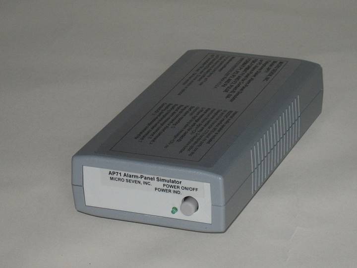
The front panel view of model AP71 is shown in the above
picture.
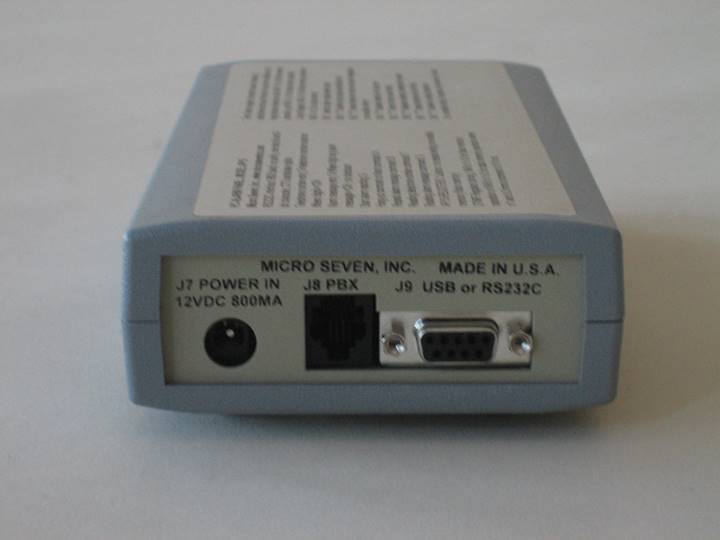
The rear panel view of model AP71 is shown in the above
picture.
INTRODUCTION
Micro
Seven Model AP71, PC-Alarm Panel or Alarm-Panel Simulator, transmits
Contact-ID, Pulse 4X2 or SIA-FORMAT alarm messages to alarm receivers by
starting commands sent at RS232C interface in PC. PC sends ASCII alarm message
for Contact-ID and Pulse 4X2 or Hexadecimal messages to AP71. PC also sends
telephone number to AP71. Since the alarm messages, telephone numbers, and
AP71Control Register for storing programming parameters are stored in
non-volatile memory in AP71, so single ASCII command at RS232C interface starts
alarm reporting process. After AP71dials a telephone number for a receiver, the
receiver answers the call and transmits the handshake tones. Depending on which
protocol mode that is selected, AP71transmits one of three protocol messages to
alarm receiver. AP71sends status messages back to PC. If the alarm reporting is
not successful, AP71transmits a different status message to PC. Transmission of
alarm messages is repeated for four times if AP71does not receive positive
acknowledge tone. The whole sequence, which involves re-dialing of telephone
number, may be repeated for three times. AP71contains audio monitor internally
to hear dialing process, handshake signals, alarm signal transmission, and
acknowledge tone/kiss-off tone. AC/DC adapter for 117VAC and interfacing cable
between PC and AP20 is provided. International AC/DC power adapter is available
as an option. Alarm receiver with FXS and FXO ports, model LS15E+TRIPLE, with
all three protocols, Contact-ID, SIA-Format, and Pulse 4X2, is available for
your alarm receiver/simulator.
SPECIFICATIONS
RS232C
interface: 9600 baud, no parity, and 8-bit character, no handshakes
Telephone number entry: D<telephone number-maximum fifteen
digits><CR>
for example D5035551212<CR> for dialing 5035551212. Note <CR> is a
carriage return.
Warning: each telephone number digit must be 0, 1, 2, 3, 4, 5, 6, 7, 8,
9, *, #, or , (comma). Note: comma adds two seconds delay between digits.
Alarm message entry for Contact-ID or Pulse 4X2:
S( in maximum 15 ASCII characters for Contact-ID or 6 ASCII characters for
Pulse 4X2)<CR> for Contact-ID or Pulse 4X2
Note: AP71prepares checksum at the end of string for Contact-ID.
Warning: ASCII character for Contact-ID must be 0, 1, 2, 3, 4, 5, 6, 7, 8, 9, B, C, D, E, or F. All other character may result in failed transmissions. Please note that ‘A’ is an illegal character for Contact-ID alarm message.
Warning: ASCII character for Pulse 4+2 must be 0, 1, 2, 3, 4, 5, 6, 7, 8, 9. All other character may result in failed transmissions.
Alarm
message entry for SIA-FORMAT:
Because alarm message for SIA-FORMAT contains binary number, input requires
hexadecimal number. It is memory write command for storing memory address 0D0H
or 0xD0. The memory address is 0D0h, 0D1H, 0D2H, 0D3H, 0D4H------. The end of
message is indicated by 0FFH.
For example, sending an address block data of 46 23 30 30 30 31 31 31 31 requires the following:
KD046KD123KD230KD330KD430KD531KD631KD731.
Note: The column parity byte is automatically prepared and attached at the end
of message by AP71.
New entry format is also
available to enter hexadecimal notation with ‘S’ header as follows:
S(hexadecimal two character
ASCII) (hexadecimal two character ASCII)-----.
For example, sending an address block data of 46 23 30 30 30 31 31 31 31 requires the
following:
S0623303030313131<CR>
Note: The column-parity byte is automatically prepared and attached at the end
of message by AP71.
Protocol selection:
W7F00 for selecting
Contact-ID, W7F01 for selecting SIA-FORMAT, or W7F02 for selecting Pulse 4X2.
Start
alarm reporting: G
Start alarm reporting process by dialing the telephone number,
receive handshake tones, transmit data blocks, and receive kiss-off tones.
Hang-up
command or Abort command: A
Turn off off-hook relay or abort alarm-reporting process.
Repeat
alarm message command: B
It transmits alarm message again. Transmitting alarm messages must
be programmed prior to sending this repeat alarm message command.
Reading
telephone-number command: T
AP20 transmits programmed telephone numbers to PC.
Reading
alarm-message command: U
AP20 transmits programmed data block to PC in hexadecimal
notation.
Continuous
message transmission mode without turning off telephone relay:
Instead of transmitting single message, multiple messages are transmitted by
sending “WACB2”.
Single
message transmission mode:
WACB0
Multiple
message transmission mode:
WACB
Protocol
selection:
W7F+(2-digit hexadecimal number):
1. Contact-ID: 00
2. Pulse: (0-5 )2, i.e. 02 for Pulse P3 mode, 32 for Pulse P4 mode, etc.
3. FSK F1: 01
4. FSK F2: 08
For
example, W7F00 for selecting Contact-ID. W7F32 for Pulse P4 mode.
Programmable
pulse mode: one mode is available for programming of kiss-off tone, handshake
tone, etc. using AP71.exe software;
-One
or two round message
-1400/2300Hz Handshake signal
-1400/2300Hz Kiss-off tone
-1800/1850/1900 carrier frequency
-checksum and verification on/off
-one/two bytes data (alarm field)-10/20/33 PPS
-3 /4 byte ID(account) field
Selection
of handshake and kiss-off signals detection for SIA-FSK FOPMAT F2:
selectable between 1400 and 2300Hz
SIA-FSK
FOPMAT F1 mode:
Signal
transmission of data block for SIA-FORMAT: 300 baud or 110 baud selectable
Pairty bit (9th bit): enabled/disabled
Wrong column parity: enabled/disabled
Acknowledge tone detection: 2025Hz for positive acknowledgement and 2225Hz for
negative acknowledgement.
Messages
received from AP71:
MESSAGE
SUCCESS
Note: “MESSAGE SUCCESS” messages are also generated when messages do not
require kiss-off tones.
MESSAGE
FAILED
CALL
FAILED
Front
panel controls:
Power
switch
Power
indicator
Audio
monitor: audio speaker is included for hearing dialing process, handshake
tones and alarm messages from alarm receivers.
Rear
panel controls:
DC
power input, DC12V, 200 mA
RS232C
interface connector, 9-pin D-sub, female
RJ11
connector
AC/DC
Adapter supplied with CS10: 117VAC +/- 5%, or 220VAC +/- 5%(for 220V unit
optional)
Dimensions: 19
cm (4") W x 4.5 cm (1.75") H x 10 cm (7.5") L
Weight:
750g (1.65 LBS)
Environmental:
Operating temperature with power on: 0 to 35 degree C, Humidity: 85% RH at 35
degree C, storage temperature and operating temperature without power on
Six-month
Warranty
Options:
1. International AC/DC power adapter
Software provided:
1.
AP71.exe for dialing
and sending alarm messages at PC. It requires PC connection via RS232
interface.
2.
Auto-dialing software
shown below for dialing and sending alarm messages without PC after set-up.
Email transmission of failed line requires PC connection.
The screen for software, AP71.EXE:
AP71 dials telephone numbers and deliver
all the alarm messages for all pulse formats, Contact-ID, SIA-FSK FORMAT F1 and
SIA-FSK FORMAT F2. Emails are originated inside PC when AP71 fails to
communicate alarm receivers. The screen shown below indicates the following:
AP71 is connected to PC, and its telephone
port is connected to line 1 of LS110, Micro Seven 4-port telephone line
simulator. Line 2 of LS110 is connected to LS15E+TRIPLE. Line 3 of LS110 is
connected to new Micro Seven model LS15K which provides SIA FSK FORMAT F2 alarm
receiver/tester.
The port 0 is set up with mode 00 for
Contact-ID protocol dialing “2” for LS15E TRIPLE at Micro Seven 4-port
telephone line simulator, model LS110-4, port 2.
The port 1 is set up with mode 02 for SIA Pulse Format P3 dialing “2’ for LS15E
TRIPLE at LS110-4, port 2.
The port 2 is set up with mode 01 for SIA FSK Format F1/300 baud dialing “2’
for LS15E TRIPLE at LS110-4, port 2.
The port 3 is set up with mode 01 for SIA FSK Format F1/110 baud dialing “2’
for LS15E TRIPLE at LS110-4, port 2.
The port 4 is set up with mode 08 for SIA FSK Format F2 dialing “3’ for LS15K
at LS110-4, port 3.The port 5 is set up with mode 32 for SIA Pulse Format P3
dialing “3’ for LS15K at LS110-4, port 4.
The email message when the test failed is
shown below:

Micro Seven, Inc.
Portland, Oregon U.S.A.