MICRO SEVEN, INC.® MODEL CS10vdsl2 TELEPHONE CABLE SIMULATOR SIMULATES A
TWISTED COPPER PAIR OF CABLE FOR DIGITAL AND ANALOG TELEPHONE LINES FOR TESTING
VDSL2 APPLICATION
Copyrights 2010 MICRO
SEVEN, INC.®
INTRODUCTION
Micro
Seven Model CS10vdsl2, Telephone Cable Simulator, provides simulation of a
twisted copper pair of cable where a single twisted copper pair cable is used
for both analog telephone and VDSL2 modems. The CS10 simulates cable
resistance, capacitance, and inductance for 0-4km of telephone cable for 1km
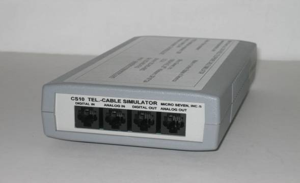
increment. The CS10 front panel contains four RJ11 connectors including digital
input (ATU-C, ADSL transceiver unit, central office end), digital output
(ATU-R, ADSL transceiver unit, remote terminal end), analog input (PSTN), and
analog output (POTS). Programming of cable distance is accomplished by RS232C
interface. Programmed parameters are stored in non-volatile memory inside CS10.
Programmed cable parameters do not change even after power to CS10 is turned
off because of use of latched relay. After CS10 programming is completed, CS10
may be carried in a case for field testing of telephone lines and/or
telecommunication equipment. Connecting
real telephone lines to CS10 for telephone cable simulation must be conducted
with power cable and RS232C interface cable removed to avoid possible high
voltage surge from telephone line onto equipment and operators.
Micro Seven, Inc.
1095-K N.E. 25th Hillsboro, OR
97124 U.S.A. phone: 503-693-6982, fax: 503-693-9742
SPECIFICATIONS
It simulates cable resistance, inductance,
and capacitance for 0-4 km for 1 km increment for 26 AWG single twisted copper
pair. Reference: ANSI T1.413-1995, Network and Customer Installation
Interfaces-Asymmetric Digital Subscriber Line (ADSL) Metallic Interface, ANSI
T1.601-1992, ISDN Basic Access Interface for Use on Metallic Loops for
Application on the Network Side of the LT (Layer 1 Specification)
Cable
characteristics: balanced, symmetrical networks
Danger:
Connecting real telephone lines to CS10 for telephone cable simulation must be
conducted with power cable and RS232C interface cable removed to avoid possible
high voltage surge on equipment and operators.
Maximum DC voltage: 250V across tip and
ring
Maximum DC current: 100 mA
Maximum AC voltage: 10dBm into 600 ohms
High voltage isolation between pins in
telephone line connector and case or AC/DC power adapter:
3kV peak when power and RS232C cables are removed.
200V peak when power and RS232C cables are connected.
All programmed parameters including
resistance and capacitance remain unchanged after power is turned off.
Front panel
controls:
RJ11 connector #1: Digital Input
(ATU-C, ADSL transceiver unit at central office end)
Connector #2: Analog Input (PSTN line
input), connection to LS15-C1 output with CO Simulator option. There are 1mh
coils at each lead between digital input and analog input.
Connector #3: Digital Output (ATU-R,
ADSL transceiver unit at remote terminal end)
Connector #4: Analog Output (POTS) to
telephone sets and modems. There are 1mh coils at each lead between digital
output and analog output.
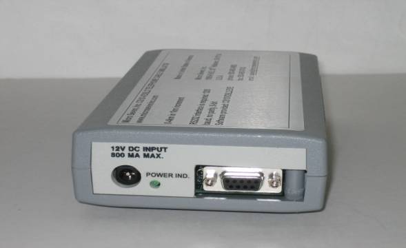
Rear panel
controls:
1. DC power
input, DC12V, 800 mA
2. RS232C
interface connector, 9-pin D-sub, female
3. Power
indicator
AC/DC Adapter: 117VAC +/-
5%, or 220VAC 100-240VAC with International AC/DC power adapter.
Dimensions: 19 cm
(4") W x 4.5 cm (1.75") H x 10 cm (7.5") L
Weight: 750g (1.65
lbs.)
Environmental: Operating
temperature with power on: 0 to 35 degree C, Humidity: 85% RH at 35 degree C.
Storage temperature: -15 to 50 degree C.
Warranty
Service:
six months limited warranty. No warranty if any factory seal is broken.
Service is performed at the factory,
usually within 5 working days.
Options:
1.International
AC/DC power adapter
2.
USB/RS232 to create new RS232 interface in your computer from USB interface
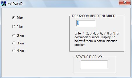
Software
provided for programming cable length
The Windows compatible software is
provided as a standard feature. The screen display when the software is run. It
requires RS232 interface in your computer. If you don’t have RS232 interface in
your computer, we provide an USB/RS232 adapter, which creates virtual RS232
interface in your computer as an optional accessory. The programmed cable
length stays as programmed value even after power is removed from CS10vdsl2.
Remove all connections including
power connection and RS232 interface to CS10 when actual PSTN telephone cable
is connected to CS10vdsl2 to avoid possible lightning damage to human bodies
and equipment.