Stand-alone alarm
panel tester/stand-alone alarm receiver without pc and with TELEPHONE LINE
SIMULATOR function, model LS100-2e
Micro Seven, Inc. ®, models LS100-2E contains Alarm-Receiver/Simulator WITH INTERNAL
LCD DISPLAYS FOR DISPLAYING RECEIVED DIGITAL dtmf-based ALARM MESSAGES including Ademco
contact-id and 4+2 protocol as an option. iT MAY ALSO BE USED AS 2-LINE GENERAL
PURPOSE TELEPHONE LINE SIMULATORS WITH RING SIGNAL, CALL PROGRESS TONES AND LOOP
VOLTAGE/LOOP CURRENT.
Copyrights Micro Seven, Inc. ® 2010
Micro
Seven, Inc. model LS100-2E contains both dtmf-Alarm-Receiver Simulator and PBX
simulator/telephone-line simulator functions. The Alarm-Receiver Simulator
function provides simulated telephone-line and alarm receiver for bench-testing
alarm panels for dtmf-based protocol including the Ademco® (registered trade
mark by ADEMCO Group, a division of Pittway) Contact ID Protocol. The simulated
telephone-line functions include generation of dual-frequency-type dial and
ring-back tones, detection of DTMF and rotary-pulse dialing pulses, and
battery-feed function. The LS100-2E provide functions of generation of
handshake tones and kiss-off tones, receiving alarm messages, check-sum
calculation, and transmitting alarm messages in ASCII format at RS232C
interface to a PC. Selections of handshake tones, kiss-off tones, alarm message
length, enabling/disabling checksum, kiss-off tone hold, enabling 2-way audio
by listen-in command, handshake tone length are provided with Windows-based
control software. LS100-2E provides testing of alarm panels for many types of
dtmf-based alarm message formats including popular Ademco Contact-ID.
Telephone-line simulator function simulates
two dial-up telephone lines for testing and demonstrating telecommunication
equipment. When a correct telephone number is dialed at line 2, ring signal is
produced at line 1. When the call is answered at other line, bi-directional
signal paths are established between two lines. The telephone-line simulator
features are very similar to ones in LS100-2A. Many features include 30HZ
square-wave ring signal, dual frequency and single frequency call progress
tones, switching extra 20 dB signal attenuation on/off, primary and secondary
telephone numbers, stutter dial tone, PBX mode, hot-line mode, distinctive
ring, network delay, and disconnect signal.
4+2 protocol option provides receiving and
displaying alarm messages with SIA pulse format.
\
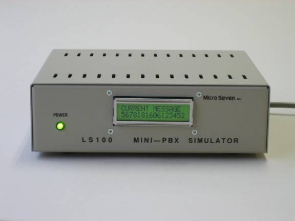
Figure 1 Picture of MICRO SEVEN-Model
LS100-2E and typical test setup
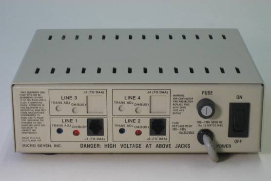
Figure 2 Picture of MICRO SEVEN-Model
LS100-2E rear panel
Features of LS100-2E
i Rugged aluminum
chassis
i Testing of
Contact-ID alarm panels
i Programmable handshake
tones, kiss-off tones, alarm message length, enabling/disabling checksum,
kiss-off tone hold, enabling 2-way
audio by listen-in command, and handshake tone length to support
many variety of dtmf-based alarm
message formats
i Direct 117VAC
input, 230VAC input is available as an option
i Testing and
decoding of Contact ID alarm message with protocol, DC05
i Handshake and
kiss-off tones
i Edit of decoded
message of event code
i DTMF or Rotary
Pulse Dialing Input
i Displaying raw or
decoded digital alarm messages and dialed telephone numbers
i Dual
Frequency-type call progress tones for dial tone and ring-back tone
i Programmable
pseudo line impairment features with 20dB insertion losses and random noises
via RS232 interface
i Either line may
be programmed as a telephone line simulator or an alarm receiver input
i RS232C interface
to transmit alarm messages to PC
i Checksum
calculation of received alarm messages
i Alarm-receiver
simulator
i Dial-up
telephone line simulator function
i 6 month warranty
i Windows software
for programming telephone line simulator and alarm receiver functions
i Alarm receiver
software for PC
i Optional 4+2
protocol format
Application and benefit of alarm
receiver
i Demonstration
and testing alarm control panels
i No alarm
receivers required for testing alarm control panels
i Complete testing
of alarm panels before the installation
i Verifying
dialing telephone numbers and digital alarm messages before installtions
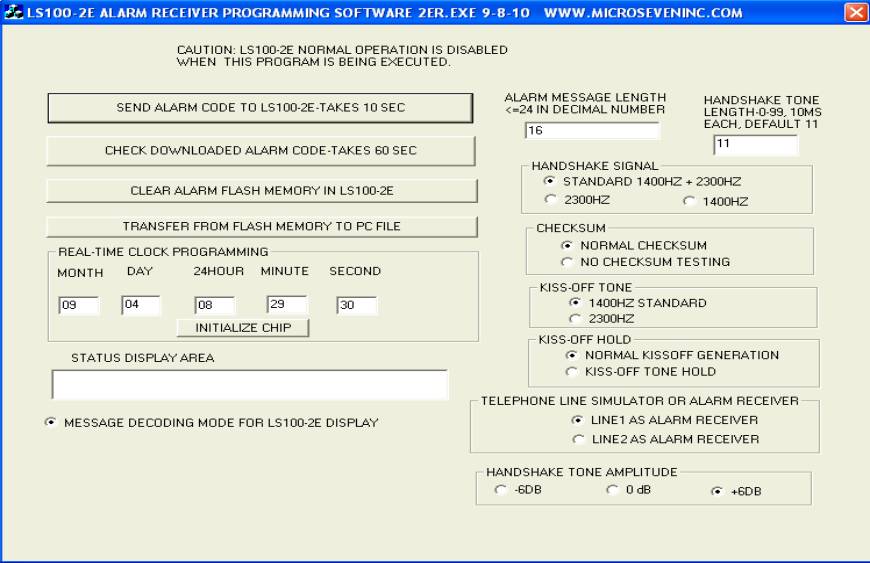
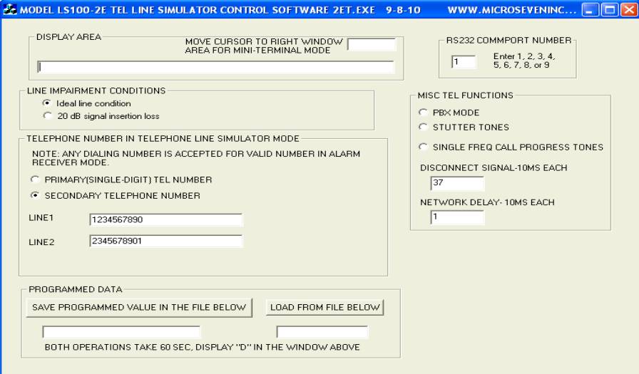
Software provided (please see screen
displays of 2ET.EXE and 2ER.EXE at the bottom)
1.
2ET.EXE with screen display shown below for programming telephone
line simulator functions including telephone number for each line, signal
insertion losses, call progress tones, network delay, disconnect signal length
, stutter tone, and PBX mode, and loading/saving programmed data. It also
programs RS232 communication port number for initial installation.
2.
2ER.EXE with the screen
display shown below for programming alarm message functions including real-time
clock, decoded alarm messages, alarm message length, handshake tone length,
handshake signal selection among 1400+2300Hz, 2300 Hz, and 1400 Hz),
checksum/nochecksum, kissoff tone selection between 1400 and 2300Hz, kiss-off
tone hold function, selection of alarm receiver or telephone line function for
each line, and handshake tone amplitude. It also includes uploading alarm
history file to PC.
3. alarm receiver software that are compatible with other alarm
receivers including CM10, LS15E, CT10, CT200, LS15E+, AR101 and AR202 is also
provided.
Operation of alarm-receivers
Traditionally,
when alarm panels are tested in the manufacturing, an alarm receiver with
telephone lines is required. The Micro Seven model LS100-2E provides both
simulated telephone lines and alarm receiver in a box so that your alarm panels
are connected directly to LS100-2E. The line 1 and 2 of LS100-2E are designated
as an alarm receiver and telephone line simulator respectively.
Connect
your alarm panel to the RJ11 connector at line 1 of LS100-2E with a regular
telephone cable. The connection of
serial interface cable between LS100-2E and PC is optional. If it is connected
and the software is executed, further decoded alarm messages are displayed on
PC screen. Even emails may be generated automatically.
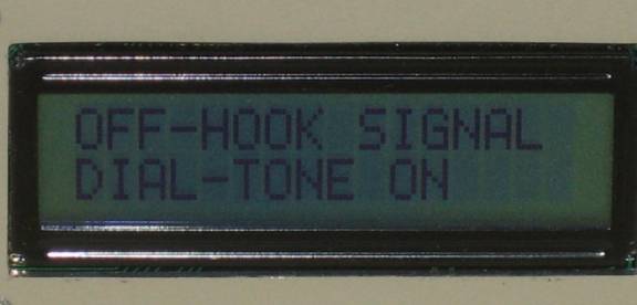
Create
an event at your alarm panel to report alarm condition. When your alarm panel
goes off-hook, “OFF-HOOK SIGNAL” and “DIAL-TONE ON” are displayed on LCD
displayed on LS100-2E.
Note: actual display area is
1”(2.5cm)x2.75”(7 cm).
OFF-HOOK SIGNAL
DIAL-TONE ON
When the
alarm panel is dialing a telephone number such as a toll-free 1800-555-1212 for
your alarm panel, “DIALING” and “18005551212” is shown on the LCD display. LS100-2E
accepts any telephone number for alarm receiver function unlike correct
telephone numbers are required to be dialed at a line when the line is
programmed as a telephone line simulator not as an alarm receiver. Since the
alarm receiver is internal, there is no ring signal generated.
DIALING
18005551212
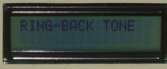
LS100-2E
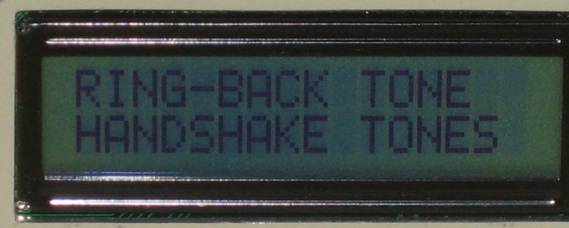
waits one second at the end of dialing process. Then it generates ring-back
tone at the line displaying “RING-BACK TONE” on the LCD display. There are two
ring-back tone periods.
RING-BACK TONE
Then
LS100-2E generates the handshake tones with 1400 and 2300 Hz displaying
“HANDSHAKE TONES” on the LCD display.
RING-BACK TONE
HANDSHAKE TONES
Then
your alarm panel transmits sixteen-digit digital alarm message to LS100-2E.
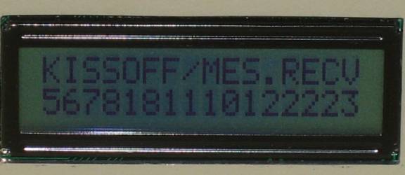
There
are two displaying modes. One mode displays raw sixteen-digit alarm messages on
the LCD display. The other mode displays decoded alarm messages including alarm
code, description of alarm code, account number, new/restaural/status, zone,
and partition number.
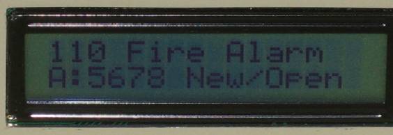
The raw
message mode displays “KISS OFF/MESS.RECV” and “567818111012223” on LCD
display. If it is the decode message mode, the display is “110 Fire Alarm” and
“A:5678 New/Open”. Where 5678 is account number and the “New/Open” is the type
of message. The display may also be either “Rest/Clos” for 3=New Restore or Closing/or “ or Status
Rp” for 6=previously-reported condition still present (Status report).
KISS OFF/MESS.RECV
5678181110122223
or
110 Fire Alarm
A:5678 New/Open
The bottom
portion of the display is then changed to : “P:12 ZON/USR:222” which indicates
the partition=12 and the zone=222. The bottom portion of the display changes
for every second between the account number with type of message and partition
with zone numbers. The decoded messages of event codes that are stored in
EEPROM inside LS100-2E may be edit by any text editor, and the changes may be
downloaded to LS100-2E by special software. Twelve maximum characters for each event
code is displayed at 16x2 LCD module.
110 Fire Alarm
P:12 ZON/USR:222
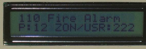
Maximum
twelve characters are only displayed on the above LCD display for a decoded
event code.
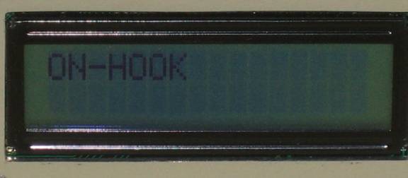
If there
was no alarm message received and LS100-2E goes on hook, it display “ON-HOOK”
shown as below.
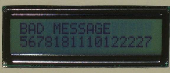
If the
checksum in the alarm message is wrong, the “BAD MESSAGE" is shown as
below with the received message.
Specifications for alarm receiver
function:
Dialing
into alarm receiver: It accepts any numbers of any DTMF digit, but the maximum pause
time between digits should be less than one seconds. The maximum dialing digit
is sixteen. Dialed numbers are shown in the LCD display.
Alarm
message detection signal power:
-13
dBm to +5 dBm per a frequency with maximum 4 dB different between frequencies
at the RJ11-C connector
Handshake
tones:
1400:
1400+/- 1Hz, -20 dBm nominal power, -30 dBm power in the line impairment mode,
duration of 100 ms +/- 1.5 ms.
2300Hz: 2300+/-2 Hz, -20 dBm nominal power, -30 dBm power in the line
impairment mode, duration of 100 ms +/- 1.5 ms
Kiss-off
tones:
1400
+/- 1 Hz –20 dBm nominal power, -30 dBm power in the line impairment mode with
duration of 750 ms
Alarm
receiver software: Window-based software is provided with LS100-2E for further
decoding alarm messages with date/time information. Also, all received alarm
messages are stored in a disk file as continuous file. The software may be able
to transmit emails into Internet when alarm messages are received at PC. All
communications via PC are done at RS232 interface.
Control
software that is provided: ls1002e.exe for the following:
1.
selection of alarm receiver or telephone line simulator for each line
2. selection of LCD display modes between raw alarm message and decoded alarm
message
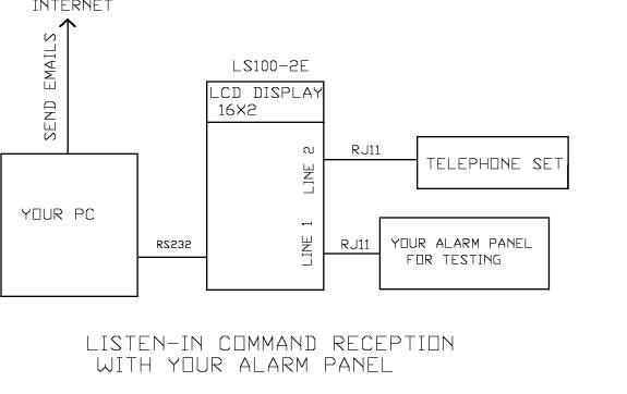
2-way audio and listen-in command: If the listen-in command with alarm
event code of 606 is received by LS100-2E, no subsequent alarm messages are
received. Ring signal is generated at other line in LS100-2E. Ring-back tone is
generated at the alarm panel. When the call is answered at the line, voice
paths are established between the other line and alarm panel in 2-way audio
path. The hang-up timer is disabled.
Reference:
Digital
Communication Standard-SIA DC-05-1999.09, Ademco Contact ID Protocol for Alarm
System Communications
Limitation
of decoded information for each event: The maximum sixteen characters for each
event code is displayed on the LCD display in LS100-2E, i.e. “101 Personal EM”
or “102 Fail-to-report” is only displayed on the LCD display because of limited
display area. Consult Micro Seven for programming your own display. Decoded
messages for the Contact-ID alarm code may be edited by using Notepad editor,
and they may be downloaded to LS100-2E for your own custom display.
Custom
LCD displays: even though the 16x2 LCD modules are standard, different LCD
modules with your own custom display area are available with 20x2, 20x4, 24x2,
40x2, and 40x4.
Alarm
message storage in EEROM in LS100-2E: Hundred received alarm messages and
real-clock data are stored in EEROM in LS100-2E for later uploading to PC.
Real-time
clock:
date and time data is stored in a history file with received alarm messages.
Alarm
control register 1 with EEROM address AE: input command “MAE00” for factory
default and setting for Contact-ID
bit 7: internal usage
bit 6: single frequency 2300Hz
handshake tone
bit 5: generation of kiss-off without
checking checksum
bit 4: single frequency 1400Hz
handshake tone
bit 3: kiss-off tone hold until PC
response
bit 2: 1:kiss-off tone with 2300Hz, 0:
kiss-off tone with 1400Hz
bit 1: internal usage
Alarm
message length register with EEROM address FD: hexadecimal 10
for Contact-ID for decimal 16, input command “MFD10” at RS232 interface using
Hyper-terminal.
Alarm
control register 2 with EEROM address FA: bit 0: 1:alarm receiver for line 1, 0: telephone line simulator for line
1, bit 1: 1: alarm receiver for line 2, 0: telephone line simulator for line 2.
Input command “MFA00” for setting line 1 and line 2 for 2-line telephone line
simulator, input command “MFA01” for setting line 1 for alarm receiver and line
2 for telephone line simulator for 2-way audio and the listen-in command.
PBX
mode is not available for alarm receiver mode.
RS232
interface, 1200 baud, eight bit data, no parity, and one stop bit format for
outputting received alarm messages in real time and uploading received alarm
history file to PC.
Specifications as telephone line
simulators:
The
selection between PBX simulator/telephone-line simulator and alarm receiver may
be made by using the control software that is provided. The PBX
simulator/telephone-line simulator function is for testing and demonstrating of
telecommunication equipment in engineering, manufacturing, and fields. It
contains dual frequency call progress tones, 30Hz square wave ring signal,
short or programmable telephone number, stutter dial tone, and distinctive ring
signals. It also contains a pseudo line-impairment mode with 20 dB insertion losses
and random noise. The LS100-2E is also equipped with a forced-disconnect
feature where disconnect signals are sent to calling and called lines.
Programmable network response delay simulates time delay after completion of
dialing. Simulated PBX mode returns dial tone after dialing 9. The secondary
call progress tone generates a single-frequency tone instead of dual-frequency
call progress tone. The programmable disconnect signal changes duration of the
disconnect-signal.
LCD
display of 2-line of sixteen characters:
Display
on-hook, off-hook status, dialing indicator, dialed telephone number,
call-progress tone indication (dial-tone, ring-back tone, and busy tone)
Note: Wrong telephone numbers that are dialed are not displayed.
Loop
start and dialing as telephone line simulator:
1. Primary telephone number method: 1 for line 1 and 2 for line 2, when the
primary telephone number method is selected, the secondary telephone number
method is disabled.
2. Secondary telephone number method, independent number for line 1 and 2 and
also primary telephone method is enabled.
Dialing signal power: -13dBm to +5dBm per a frequency with maximum 4dB
difference between frequencies.
DTMF dialing detection time: 45 ms
Pulse dialing: Break period: 45 to 75 ms (60 ms nominal), make period: 30 to 60
ms (40 ms nominal)
Note:
selection between primary and secondary telephone number is done by dialing
process or using by control software.
20 dB signal insertion loss:
When a number
of 00 and line-number is dialed, signal insertion losses between lines is 20dB.
Ideal line condition mode:
When
a number of 09 and a line number are dialed, the insertion loss between lines
becomes only 1 dB. This is the factory default condition
Ring
signal: 30Hz-square Wave,
100V RMS
Distinctive ring signal features:
The following
distinctive ringing pattern is enabled instead of standard 2 sec on/ 4 sec off
ringing pattern:
(a). Dialing 0
* 1 + (line number): 2 sec on/ 4 sec off
(default condition)
(b). Dialing 0
* 2 + (line number): 0.8 sec on, 0.4 sec off, 0.8 sec on, 4 sec off
(c). Dialing 0
* 3 + (line number): 0.4 sec on, 0.2 sec off, 0.4 sec on, 0.2 sec off, 0.8 sec
on,
4 sec off
(d). Dialing 0
* 4 + (line number): 0.3 sec on, 0.2 sec off, 1 sec on, 0.2 sec off, 0.3 sec on,
4 sec off
Hot
line mode
Common specifications for telephone
line simulators and alarm receivers:
LCD
display of 2-line of sixteen characters:
display
on-hook, off-hook status, dialing indicator, dialed telephone number,
call-progress tone indication (dial-tone, ring-back tone, and busy tone)
Note: all dialed telephone numbers that are dialed are displayed.
Transmit Power Adjustment: A potentiometer for each line,
accessible through a rear panel, provides a control range of 0 to -40
dB(maximum at full clockwise).
Battery-feed
voltage (loop voltage): (same as the telephone line simulator function): -20 volts:
Off-hook
impedance requirement: 400 ohms maximum DC, 600 ohms nominal AC
(same as the telephone line simulator function)
Call
Progress Tones: (same as the telephone line simulator function)
Standard dual-frequency call progress tones, nominal -16 dBm.
Dial Tone: 350 Hz + 440 Hz, continuous unless programmed for stutter dial tone
Ring-back Tone: 440 Hz + 480 Hz, 2 sec ON/4 sec OFF.
Busy Tone: 480 Hz + 620 Hz, 0.5 sec ON/0.5 sec OFF.
Secondary
Call Progress Tones: Single-frequency tone of 480 Hz
The selection between dual frequency call frequency and single frequency type
is done by control software.
Stutter dial tone: The stutter dial tone with three of 0.1 seconds on/off period
following with continuous dial tone.
The restoration of factory default is done by dialing 04#
when the line is programmed as a telephone line simulator:
The factory
default conditions are as follows:
-alarm receiver at line 1 and telephone line
simulator at line 2
-primary (short) dialing method (single
digit).
-Ideal line condition mode.
-Continuous dial tone, not stutter dial tone.
-Secondary telephone number is set
for1234567890 for line 1 and 2345678901 for line 2
-No network response delay
-Disconnect signal of 320 ms
-Secondary call progress tone instead of dual
frequency call progress tones
Simulated
PBX Mode:
The simulated PBX mode where dial tone returns after dialing 9:
Line characteristics: (same as the telephone line simulator function)
Input impedance at 1 k Hz: 600 ohms +/- 5%
Accuracy in frequency component: +/- 1%.
Forced
called-party disconnect, programmable network response delay, programmable
disconnect signal, and simulated PBX mode are also available.
Line Input Jacks: USOC-RJ11-C, standard modular phone jack (same as the
telephone line simulator function) located on rear panel
Programmable
disconnect-signal, network response delay:
The programmable disconnect signal is interruption of loop current at the end
of call when one line hangs up. The network response delay is inserted between
completion of dialing and ring signal.
Power Switch: on rear panel
Calibration: not required
because digitally synthesized tones
Power Requirements:
100-130 VAC,
50/60 Hz, 18 watts maximum
Fuse: fuse holder is located at rear panel: 0.15A, 3AG, SLO-BLO
Dimensions:
8.35 in (21.2
cm) Wide x 2.5 in (6.35 cm) High x 7.25 in (18.4 cm) Long.
Line Status Display: red LED for each line to indicate off-hook status
(continuous on)
or ringing
status (blinking) on rear panel
Power On Indicator: green LED display on front panel.
Weight: 3.5 lbs. (1.6 kg.)
Environmental: Operating
temperature: 0 to 35 degree C, Humidity: 85% RH at 35 degree C
Warranty/Service: 6 months
limited warranty. No warranty if any factory seal is broken. Service is
performed at the factory, usually within 5 working days.
Options
and Accessories: 1. 230V power
2. 4+2 protocol option
SIA Pulse Format P3 in SIA DC-02-1992.02 (R2000.05), section 4.1.3 Pulse
Format P3 is provided.
Note: LS100-2E generates kissoff tone for 4+2 mode first. If there is no 4+2
communication for four seconds, contact-ID handshake is generated.
Four digits for account number, one digit for event, and last digit for zone.
One period consists of 1900 Hz on for 25ms and tone-off for 25ms.
Handshake signal: 1400Hz tone for one second long.
Kiss-off tone: 1400Hz tone for one second long.
Double transmission is required for generating kissoff tone.
Listen-in feature is supported in a same way as contact-ID mode by ringing
telephone set at line 2 when personal emergency, 2 way voice with zones 1
through 9 is received.
Event codes that are supported and are decoded for LCD display:
01,02,03, 04 --- 09 personal emergency, 2 way voice –zones 1 through 9
40 - AC loss
50 – Restoral AC Loss
61-69, loss of supervision, zones 1-9
71-79, restoral –loss of radio supervision
41-49, low battery with zones 1 –9
51-59, restoral low battery with zones 1-9
30, test report
Micro Seven, Inc. ®
1095-K N.E. 25th Hillsboro, OR,
U.S.A.
Home Page: www.microseveninc.com
Email: sales@microseveninc.com
Other
alarm receivers and related products