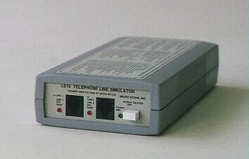
Micro Seven Inc.® model
LS15-E+ includes
an alarm-receiver simulator
and alarm-receiver
copyrights Micro Seven, Inc.®, 2007, 2008, 2009, 2010
Micro
Seven, Inc. model LS15-E+ contains Alarm-Receiver Simulator/Tester and alarm receiver.
The Alarm-Receiver Simulator/Tester function provides simulated telephone-line
and alarm receiver for testing and demonstrating alarm panels for the Ademco®
(registered trade mark by ADEMCO Group, a division of Pittway) Contact ID
Protocol. The simulated telephone-line functions include generation of
dual-frequency-type dial and ring-back tones, detection of DTMF and
rotary-pulse dialing pulses, and battery-feed function. The LS15-E+ provides
functions of generation of handshake tones and kiss-off tones, receiving alarm
messages, check-sum calculation, and transmitting alarm messages in ASCII
format at RS232C interface to a PC. It operates with an AC adapter that is
provided with LS15-E+. An alarm panel may be connected directly bypassing
telephone companies at line 1 or may be connected to telephone lines at line 2.
The Alarm-Receiver Simulator function is available at line 1, and regular alarm
receiver function is available as CPE port at line 2. Caller-ID receiver is
available for its option in Bellcore and ETS caller-ID standard. Alarm receiver
software is provided.
MICRO SEVEN-Model LS15-E+, Alarm Receiver
Simulator/PBX Simulator
Features
of Alarm-Receiver Simulator portion of LS15-E+
i Small, 4" x 1.75" x 7.5"
i AC/DC Operation
i Low cost, and
portable
i Connect alarm
panel directly or via telephone lines
i Security
Industry Association’s Ademco® Contact ID Protocol
i Handshake and
kiss-off tones
i DTMF or Rotary
Pulse Dialing Input
i Primary or
secondary (programmable to 18 digit) telephone number
i Dual
Frequency-type call progress tones for dial tone and ring-back tone
i Programming of
amplitude of handshake and kiss-off tones to simulate the long-distance
telephone-line condition
i No calibration
required for frequency and amplitude adjustment of handshake, kiss-off, and
call progress tones
i RS232C interface
to transmit alarm messages to PC and the control software to program many
parameters including telephone numbers
i Checksum
calculation of received alarm messages
i Alarm-receiver
simulator from line 1 and regular alarm receiver at line 2
i Battery-feed
(loop current)
i Caller-ID
receiver option
i Car battery
adapter and 230 volt power options
i Windows-based
alarm receiver software included
i 6 month warranty
i Windows-based
programming software included
i Dialing and
delivering received alarm messages to other alarm receivers are available as an
option
i Option for
dialer functions that transmits received Contact-ID messages to another
Contact-ID alarm receiver
(new model LS15E+_DIALER)
Application
and benefit of alarm receiver
i Demonstration
and testing alarm control panels at factories and fields
i No alarm
receivers required for testing alarm control panels
i Complete testing
of alarm panels before the installation
Introduction
Traditionally, when alarm panels are tested in the
manufacturing or demonstrated in the sales offices, alarm receiver with two
public telephone lines are required in addition to a computer. The Micro Seven
model LS15E+ eliminates an alarm receiver and two telephone lines by combining
both of telephone line simulator and alarm receiver functions for the
application. Here, an alarm panel is connected to the line 1 of LS15E+. The
RS232C port of a PC is connected to the rear panel connector of LS15E+ with
special cable and connector that are provided with LS15E+. Micro Seven’s LS15E+
control software provides a tool to display incoming alarm messages. First, the
alarm panel goes off-hook at line 1. The loop current is flowing at the line 1. Then, the alarm panel dials either primary
telephone number “2” (single digit) or secondary telephone-number that is
assigned for line 2(programmable one) depending on which telephone number
scheme is selected. When the dialed number is correct, the LS15E+ provides
ring-back tone for two seconds. Then, there is no sound for four seconds. And
ring-back tone is generated for two seconds. After 0.6 seconds, the LS15E+
transmits handshake tones of 1400 and 2300Hz for 100 ms each separated with 100
ms silence period. When the alarm panel receives the handshake tones, the alarm
panel transmits a string of alarm message in DTMF tones with a check-sum at the
end. When the alarm message with correct check-sum is received by LS15E+, it
transmits the kiss-off tone to the alarm panel. LS15E+ also transmits the ASCII
equivalent of the alarm message at the RS232C interface to the PC. Then, the
alarm panel either transmits a new alarm message after a short delay or hangs
up with the telephone line to terminate the call. If the alarm panel did not
receive the kiss-off tone, the alarm panel may repeat transmitting the same
alarm message four times. When LS15E+ sees the on-hook-state, it turns off the
loop current for a few hundred milliseconds as a disconnect signal. Then,
LS15E+ is now ready for a new call from the alarm panel. LS15E+ is compatible
with the Ademco ® Contact ID Protocol for Alarm System Communications.
Programmed parameters are restored upon powering off and on unless noted.
The line 2 of LS15E+ contains CPE (customer provided
equipment) circuit to interface PBX inside line. If there is ring signal input
at line 2, an off-hook relay is turned on to represent off-hook condition.
After short time delay, LS15E+ transmits handshake tones of 1400 and 2300Hz in
100 ms each separated with 100 ms silence period. The rest of alarm receiver
sequence is the same as for line 1 as follows: when the alarm panel receives
the handshake tones, the alarm panel transmits a string of alarm message in
DTMF tones with a check-sum at the end. When the alarm message with correct
check-sum is received by LS15E+, it transmits the kiss-off tone to the alarm
panel. LS15E+ also transmits the ASCII equivalent of the alarm message at the
RS232C interface to the PC. Then, the
alarm panel either transmits a new alarm message after a short delay or hangs
up with the telephone line to terminate the call. If the alarm panel did not
receive the kiss-off tone, the alarm panel may repeat transmitting the same
alarm message four times. When the alarm panel hangs up the call, it produces
disconnect signal that interrupts loop current at line 2. Then, LS15E+ turns
off the off-hook relay. Then, LS15E+ is now ready for a new call from the alarm
panel. LS15E+ is compatible with the Ademco ® Contact ID Protocol for Alarm
System Communications. Programmed parameters are restored upon powering off and
on unless noted.
Standard alarm receiver software, that is provided
at no charge, “as is” with no support, no liability, and no support from Micro
Seven,, in Windows operating system that receives and decodes caller-ID
information and Contact ID alarm messages displays caller’s telephone number,
name, date, nature of alarm messages on PC screen. The software also stores the
same information as a text file. Any additional software requirement is custom.
Internal rechargeable battery option is available (new).
SPECIFICATIONS
Telephone number:
(same as the
telephone line simulator function)
Telephone numbers:
1. Primary telephone number
2. Secondary telephone number
DTMF dialing signal
power: -13dBm to +5dBm per a frequency with maximum 4dB difference between
frequencies.
Pulse dialing: Break
period: 45 to 75 ms (60 ms nominal), make period: 30 to 60 ms (40 ms nominal)
DTMF detecting signal
power for alarm messages: -23dBm to +5dBm per a frequency with maximum 4dB difference
between frequencies
Alarm message DTMF
signal on time (Burst ON time): 50 ms minimum
Alarm message DTMF
signal off time (Burst OFF time): 50 ms minimum 400 ms maximum
Note: Contact ID
protocol requires Burst ON and OFF times to be 50 ms minimum and 60 ms maximum.
Handshake tones:
1400: 1400+/- 1Hz,
duration of 100 ms +/- 1.5 ms, silence period of 100 ms +/- 1.5 ms, and
2300Hz: 2300+/-2 Hz
duration of 100 ms +/- 1.5 ms
Kiss-off tones:
1400 +/- 1 Hz with
duration of 750 ms
Kiss-off and
handshake tones amplitude: selectable among -14 dBm, -20 dBm, and -30 dBm by
control software
Line characteristics:
(same as the telephone line simulator function)
Battery-feed
voltage at line 1: (loop voltage): -20 volts
Off-hook impedance
requirement at line 1: 400 ohms maximum DC, 600 ohms nominal AC(same as the
telephone line simulator function)
Call Progress Tones
at line 1: single frequency or dual frequency type selected by control software
Stutter dial tone at
line 1: selected by control software
Line Input Jacks at
line 1 and line 2: USOC-RJ11-C, standard modular phone jack
Programmable
disconnect-signal at line 1: by control software
CPE port at line 2:
High voltage isolation: 1500VRMS between lines and RS232C connector.
Ring signal detector:
opto-coupler
Signal isolation:
telephone coupling transformer
Off-hook impedance: 50 ohms typical
High ON-hook
impedance is obtained by off-hook mechanical relay.
Handshake tone is
produced after 1.8 seconds when the off-hook relay is turned on.
RS232C Interface:
Speed: 1200 baud, with one stop bit, no parity bit
The interface
signals: Receive Data, Transmit Data, Data Set Ready, Clear-to-send, and
ground. The Data Terminal Ready signal is forced high at LS15E+ meaning that a
PC is always ready to receive data from LS15E+.
Connector: 9-pin D-sub on LS15E+ the rear panel
Cable(9-pin M/9-pin
F) is provided.
Received alarm
messages are computed for the checksum.
AC/DC
Adapter(provided with LS15E+): 117VAC +/- 5%, or 230VAC +/- 5%(for optional
230V AC/DC Adapter)
AC/DC Adapter or Car
Battery Adapter input: 12VDC unregulated, 800mA maximum
Line Status Display:
red LED for each line to indicate off-hook status (continuous on)
Calibration: not
required because digitally synthesized tones
Power-On Indicator:
green LED display
Dimensions: 19 cm
(4") W x 4.5 cm (1.75") H x 10 cm (7.5") L
Weight: 400g (0.8
LBS.)
Environmental:
Operating temperature: 0 to 35 degree C, Humidity: 85% RH at 35 degree C
Warranty/Service: 6
months limited warranty. No warranty if any factory seal is broken. Service is
performed at the factory, usually within 5 working days.
Options and Accessories:
Car Battery Adapter
230V input AC/DC
Adapter (117V input unit is a standard.)
Internal rechargeable
battery option
LS15E+_DIALER, a new model
number, for dialing telephone numbers and transmitting alarm messages to
another alarm receiver
Reference: Digital Communication Standard-SIA
DC-05-1999.09, Ademco Contact ID Protocol for Alarm System Communications
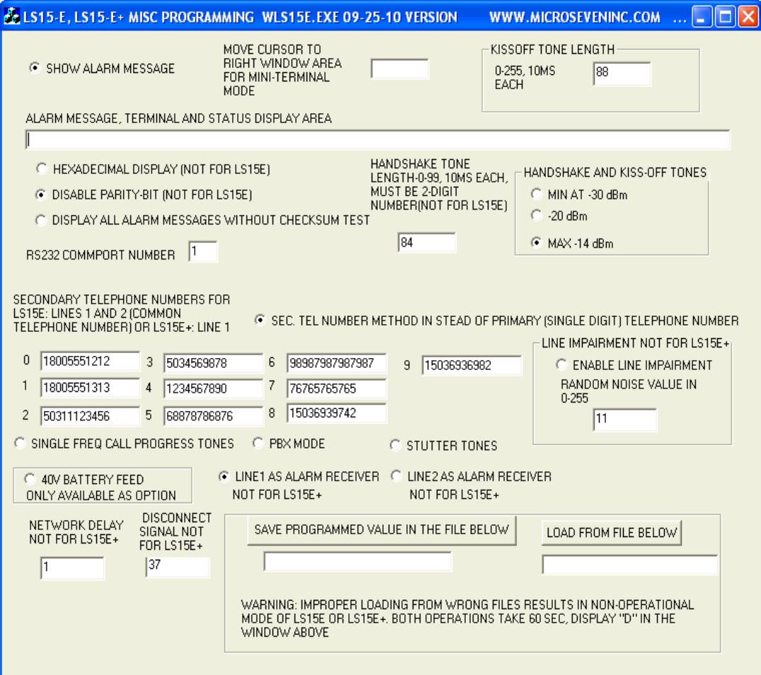
Programming of
kiss-off tone length, kiss-off and handshake amplitude, single frequency/dual
frequency call progress tones, PBX mode, stutter tone, nine different telephone
numbers, selection of single-digit telephone number and secondary telephone
number is available in standard Windows-based control software with the screen
display shown below. Loading of default file and saving your programmed
parameters including telephone numbers as PC disk files are also provided.
Caller-ID receiver
option:
- It reads FSK caller-ID data
between ring signal. Incoming
caller’s telephone number with date/time and names (if available) is
generated to PC along with alarm messages at line 2, PBX line input. It
supports both single or multiple message formats in Bellcore (US and
Canada) and ETS modes. Control characters preceding caller-ID name and
telephone numbers may be masked for their output to PC.
- It also reads DTMF caller-ID data
before ring signal or between ring period. Incoming caller’s telephone
number s1, s2, s3,--- is output to PC with the format D(s1)(s2)(s3)----C.
Alarm receiving software: Windows-based
Note: we provide no liability using LS15E+ and alarm
receiving software to all people and companies including alarm panel users,
alarm central station, telephone companies, and all distributors.
A typical PC display
is shown below: Note that the first line is date/time data that is received
from caller-ID, and the date/time on the fifth line is derived by PC. The
second and third lines are also from caller-ID. Alarm message number is incremented
by each alarm message that is received. The sixth line shows a complete alarm
message.
Receiving caller-ID data---- Date/time: 03231047
Caller's telephone number: 5036936982
Caller's name: MICRO SEVEN INC
Alarm message
number: 12354
Fri Mar 23
10:47:10 2007
Alarm message: 1234181131010158
Acount number: 1234
Event qualifier: New Event
Event code: 131 Perimeter-Burglar Alarm
User/Zone Number: Zone 015
Partition number: 01
The alarm message file, “al” may be read
by another application in a same PC while LS15E+ is running programs. A sample
c++ program below open the file “al” and read alarm messages, which must be
compared with previous read alarm message file to find out any new alarm
message. Note that the file “al” is generated by LS15ES0A.EXE.
The C++ program below uses a timer
function to open, read, and close the file “al” periodically to check whether
any new alarm message.
SetTimer(1,5000,NULL); //timer should be set up somewhere in your program.
//this one is set up for every five seconds, do not set up timer too short
void CTest1Dlg::OnTimer(UINT nIDEvent)
{
hFile2=CreateFile(TEXT("./al"), //open file “al”
GENERIC_READ,
FILE_SHARE_READ,
NULL,
OPEN_EXISTING,
FILE_ATTRIBUTE_NORMAL|FILE_FLAG_SEQUENTIAL_SCAN,
NULL);
ReadFile(hFile2,displaypointer,100000,numberread,NULL); //read an entire alarm message file
CloseHandle(hFile2); //close file “al”
UpdateData(FALSE);
CDialog::OnTimer(nIDEvent);
}
Micro Seven, Inc. ®
Hillsboro, OR, U.S.A.
Home Page: www.microseveninc.com
Email: sales@microseveninc.com
Other
alarm receivers and related products