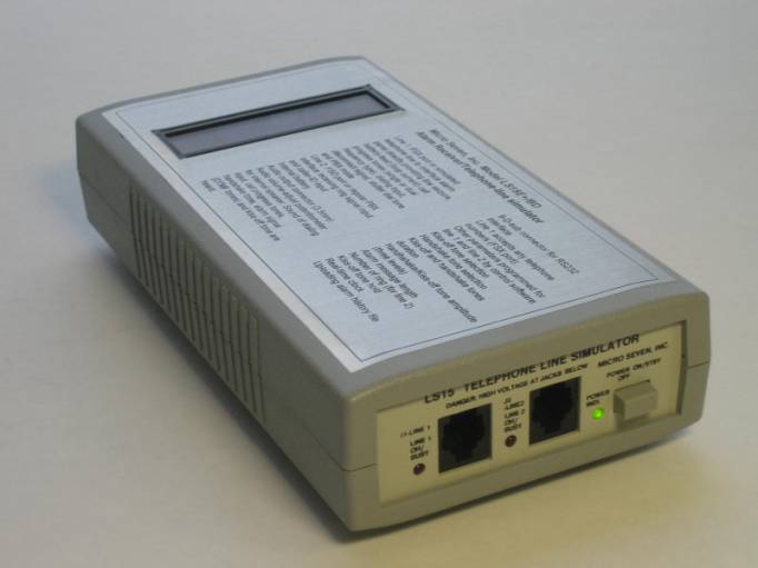
Micro Seven Inc.® model
LS15-E+/BD includes an alarm-receiver simulator with telephone line simulator and
alarm-receiver with LCD display, caller-ID receiver, flash memory for alarm
messages, real-time clock, and caller-ID receiver
Copyrights Micro Seven, Inc.®, 2010
INTRODUCTION
Traditionally, when alarm panels are tested in the
manufacturing or demonstrated in the sales offices, alarm receiver with two
public telephone lines are required in addition to a computer. The Micro Seven
model LS15E+/BD eliminates an alarm receiver and two telephone lines by
combining both of telephone line simulator and alarm receiver functions.
LS15E+/BD also contains rechargeable battery, and field-testing of alarm panel
without using AC power is not required. It also contains multi-line
alpha-numeric LCD display for showing decoded alarm and other test messages, so
PC and RS232 interface is not required to see received alarm messages. It also
contains caller-ID receiver and real-time clock with battery circuit.
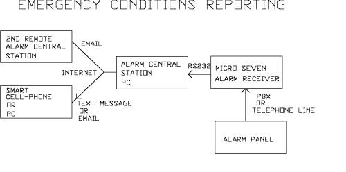
A Contact-ID type alarm panel may be connected to the line
1 of LS15E+/BD or may be connected to line 2 via PSTN or PBX telephone network.
The RS232C port of a PC is connected to the rear panel connector of LS15E+/BD
with special cable and connector that are provided with LS15E+/BD for
programming LS15E+/BD and displaying caller-ID and decoded alarm messages at
PC. Our provided control software is a tool to display incoming alarm
messages. First, the alarm panel goes
off-hook at line 1. The loop current is flowing at the line 1. The display shows “OFF-HOOK SIGNAL DIAL TONE ON”. Then, the alarm panel dials
a pre-programmed telephone number, and the display shows the number. Note that
LC15E+/BD accepts any telephone number. The pause after entering telephone
numbers is a sign of end of telephone number. Then ring-back tone is generated
with display showing “RING-BACK TONE” for two seconds. After 0.6 seconds, the LS15E+/BD transmits
handshake tones of 1400 and 2300Hz for 100 ms each separated with 100 ms
silence period. The display shows “HANDSHAKE TONES”. When the alarm panel
receives the handshake tones, the alarm panel transmits a string of alarm
message in DTMF tones with a check-sum at the end. When the alarm message with
correct check-sum is received by LS15E+/BD, it transmits the kiss-off tone to
the alarm panel. The display shows “KISSOFF TONE” and alarm messages with or
without decoded messages depending on setting. LS15E+/BD also transmits the
ASCII equivalent of the alarm message or decoded alarm messages at the RS232C
interface to the PC. Then, the alarm panel either transmits a new alarm message
after a short delay or hangs up with the telephone line to terminate the call.
If the alarm panel did not receive the kiss-off tone, the alarm panel may
repeat transmitting the same alarm message four times. When LS15E+/BD sees the
on-hook-state, it turns off the loop current for a few hundred milliseconds as
a disconnect signal. Then, LS15E+/BD is now ready for a new call from the alarm
panel. LS15E+/BD is compatible with the Ademco ® Contact ID Protocol for Alarm
System Communications. Programmed parameters are restored upon powering off and
on unless noted.
The line 2 of LS15E+/BD contains CPE (customer provided
equipment) circuit to interface PBX inside line. If there is ring signal input
at line 2, the display shows “RING SIGNAL” and caller-ID data if there is
incoming caller-ID data. Then an off-hook relay is turned on to represent
off-hook condition. After short time delay, LS15E+/BD transmits handshake tones
of 1400 and 2300Hz in 100 ms each separated with 100 ms silence period. The
rest of alarm receiver sequence is the same as for line 1 as follows: when the
alarm panel receives the handshake tones, the alarm panel transmits a string of
alarm message in DTMF tones with a check-sum at the end. When the alarm message
with correct check-sum is received by LS15E+/BD, it transmits the kiss-off tone
to the alarm panel. LS15E+/BD also transmits the ASCII equivalent of the alarm
message at the RS232C interface to the PC.
Then, the alarm panel either transmits a new alarm message after a short
delay or hangs up with the telephone line to terminate the call. If the alarm
panel did not receive the kiss-off tone, the alarm panel may repeat
transmitting the same alarm message four times. When the alarm panel hangs up
the call, it produces disconnect signal that interrupts loop current at line 2.
Then, LS15E+/BD turns off the off-hook relay. Then, LS15E+/BD is now ready for
a new call from the alarm panel. LS15E+/BD is compatible with the Ademco ®
Contact ID Protocol for Alarm System Communications. Programmed parameters are
restored upon powering off and on unless noted.
SPECIFICATIONS
Specifications
of alarm receiver function:
Dialing at line 1: accepts any telephone numbers with pause at
the end
DTMF dialing signal power:
-13dBm to +5dBm per a frequency with maximum 4dB difference between
frequencies.
Pulse dialing:
Break period: 45 to 75 ms (60 ms nominal), make period: 30 to 60 ms (40 ms
nominal)
DTMF detecting signal power for alarm messages: -23dBm to +5dBm per a frequency with maximum 4dB
difference between frequencies
Alarm message DTMF signal on time (Burst ON time): 50 ms minimum
Alarm message DTMF signal off time (Burst OFF time): 50 ms minimum 400 ms maximum
Note: Contact ID
protocol requires Burst ON and OFF times to be 50 ms minimum and 60 ms maximum.
Handshake
tones:
1400: 1400+/- 1Hz,
duration of 100 ms +/- 1.5 ms, silence period of 100 ms +/- 1.5 ms, and
2300Hz: 2300+/-2 Hz
duration of 100 ms +/- 1.5 ms.
Selectable among
1400, 2300, and 1400/2300 (factory default) by using control software,
LS15EBD.EXE. Duration of handshake tone
and pause time between handshake tones are programmable by using control
software, LS15EBD.EXE.
Kiss-off
tones:
1400 +/- 1 Hz with
duration of 750 ms (factory default)
Duration is
programmable by using control software, LS15EBD.EXE.
Kiss-off and handshake tones amplitude: selectable among -14 dBm, -20 dBm (factory default), and
-30 dBm by control software
Loop voltage at line 1: (loop voltage): -20 volts (factory default) or –40 volts selectable by
control software, LS15EBD.EXE.
Off-hook impedance requirement at line 1: 400 ohms maximum DC, 600 ohms nominal AC
Call Progress Tones at line 1: dual frequency type
Line Input Jacks at line 1 and line 2: USOC-RJ11-C, standard modular phone jack
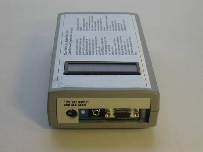
Audio monitor and Audio output: Internal audio speaker, volume adjust potentiometer on rear panel, and
audio output connector (3.5mm) are equipped to hear dial tone, dialing
telephone numbers, handshake tone, alarm signal, and kiss-off tones.
Caller-ID receiver: accepts both
single message format and multiple message format. American bell-core type
caller-ID data is received by internal caller-ID receiver and displayed on
internal LCD display. Data may also be transmitted at RS232 interface.
Real-time clock:
battery-backed real time clock data is stored with received alarm message and
caller-ID data as alarm history data in EEROM.
EEROM for storing alarm history file: total 24 kbytes for storing 64 byte each of alarm messages with
caller-ID and real-time clock data. The data may be uploaded with the control
software.
LCD Display: 2 lines of 16-character
Internal Battery: Ni-cad 7.2 Volt, minimum two-hour operation. The green
power indicator also shows status of battery power. It flashes when it requires
recharging during battery. The battery is recharged when the power switch is
off.
CPE port at line
2:
High
voltage isolation: 1500VRMS between lines and RS232C connector.
Ring signal detector:
opto-coupler
Signal isolation:
telephone coupling transformer
Off-hook impedance: 50 ohms typical
RS232C Interface:
Speed: 1200 baud, with one stop bit, no parity bit
The interface
signals: Receive Data, Transmit Data, Data Set Ready, Clear-to-send, and
ground. The Data Terminal Ready signal is forced high at LS15E+/BD meaning that
a PC is always ready to receive data from LS15E+/BD.
Connector: 9-pin D-sub on LS15E+/BD the rear panel
Cable(9-pin M/9-pin
F) is provided.
AC/DC Adapter:
117VAC(standard), or 100-240VAC (International AC/DC power adapter option)
Line Status Display:
red LED for each line to indicate off-hook status (continuous on)
Calibration: not required because digitally synthesized tones
Power-On Indicator:
green LED display
Dimensions:
19 cm (4") W x 4.5 cm (1.75") H x 10 cm (7.5") L
Weight: 400g (0.8
LBS.)
Environmental:
Operating temperature: 0 to 35 degree C, Humidity: 85% RH at 35 degree C
Warranty/Service:
6 months limited warranty. No warranty if any factory seal is broken. Service
is performed at the factory, usually within 5 working days.
Options
and Accessories:
International AC/DC
power adapter with four different power plugs (US, UK, Australia, and Europe)
for 100-240VAC
USB/RS232 adapter
Reference: Digital Communication Standard-SIA DC-05-1999.09, Ademco Contact ID
Protocol for Alarm System Communications
Software:
LS15EBD.EXE for programming real-time clock, alarm message
format, handshake/kissoff tones, etc.
LS15ES0.EXE for receiving alarm signals at PC (NOTE:
software is not required for displaying alarm messages in LS15E+/BD.)
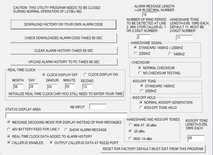
Software description of LS15EBD.EXE
Alarm message length (for programming non-Contact-ID type )
Enter
a number of new alarm message length in 2-digit number. It must be less than or
equal to decimal 24. Contact-ID requires decimal 16.
checksum
Normal checksum
testing by LS15E+/BD is a factory default condition. Kiss-off tone is not
generated unless checksum is good. Select “No checksum testing” for generating
kissoff tone without checking checksum.
Kiss-off and handshake tone amplitude
Kiss-tone selection
(for programming non-Contact-ID type)
The standard kiss-off
tone for Contact-ID is 1400 Hz. 2300 Hz kiss-off tone may be selected instead
of 1400 Hz.
Handshake tone selection (for programming non-Contact-ID type)
The standard handshake tone is 1400 and 2300 Hz. It
may be selectable 1400 only, or 2300 Hz only.
Length of kiss-off and handshake tones is independently programmable by entering numbers in the
edit window. Each count represents 10 ms.
Kiss-off tone hold: When
the “kiss-off tone hold” is on, kiss-off tone generation is hold until
receiving acknowledge ASCII "a" from PC within 1.25 seconds.
Reset for factory
default
Alarm code: Data for decoding events is stored in EEROM inside
LS15E+/BD. The factory default file is “alarmcode.txt”. You can edit the alarm
code for each event to create your own decoded message. Click the “Download”
button, and the new alarm code may be downloaded into LS15E+/BD. Click the
“Click downloaded alarm code” for verify that alarm code that is stored in
LS15E+/BD is the same as “alarmcode.txt”.
Alarm History file: Alarm message data with real-time clock data, caller-ID Data
for decoding events, which is stored in consecutively in LS15E+/BD, is uploaded
into PC as “alarmhistory.txt”.
Click the button
“Clear alarm history” for erasing alarm history file inside LS15E/BD.
The following is a list of alarm
history file. The format of history data includes:
Month-day, hour (in 24 hr
format):minute: second follows with caller-ID data and raw contact-ID data
beginning with *. The first two lines are history file data at line 2 with
caller-ID. The latter two lines are from line 1.
06-28 14:42:14
010112301234567890ABCDEFGHIJK *3456181140123452
06-28 14:42:21
010112301234567890ABCDEFGHIJK *5678181110122223
06-28 14:43:02 *5678181110122223
06-28 14:43:10 *7890181131111116
Real-time clock
programming: Normally, the clock
display is off, and the display is updated for every second when the “CLOCK
DISPLAY OFF” is selected. Under this circumstance, normal operation of
LS15E+/BD should be turned off; otherwise, there will be erroneous operation of
LS15E+/BD.
“Initialize real-time
clock” button needs to be pushed when the real-time clock loses power and data.
In this case, enter new date and time at the edit windows.
When the “REAL-TIME
CLOCK DATA ADDED TO ALARM HISTROY” is on, real-time clock data is added to the
history alarm message data in LS15E+/BD.
Status display area: The status display area shows progress of the control
software, alarm messages, and special terminal operation.
Raw alarm messages
are displayed in the status display area when “show alarm message” is on.
When the cursor is in
the “KB input” edit window, typed keyboard data is output at RS232 and to the
status display area. Received characters at RS232 is displayed in the status
display area for creating Hyper-terminal mode.
40V battery feed: Loop voltage becomes 40 Volt minimum when the “40V battery
feed” is on. Otherwise, the loop voltage is –20 Volt.
Caller-ID Receiver: Receiving
caller-ID data is enabled when “caller-ID enabled” is selected. Received
caller-ID data at RS232 is on when the “output caller-ID data at RS232 port” is
on.
Display:
2x 16 character alphanumeric LCD
display
The
PC screen when the LS15EBD.EXE runs is shown below with factory default
condition except real-time clock setting.
OPERATION
First-time
operation without alarm panel
The following procedure requires a telephone set with
memory dial for dialing sixteen digits of telephone number. Please follow the
procedures below:
1. Connect AC/DC adapter to correct AC power. Connect the power cable to
LS15-E+/BD. Turn on the power switch on LS15-E+/BD front panel.
2. Attach a telephone set at line 1 of LS15-E+/BD.
3. Program telephone set to dial 1234181131010158 for memory dial.
4. Lift telephone receiver, hear dial tone. The displays shows “OFF-HOOK
SIGNAL, DIAL-TONE ON”. Dial ‘2”, and
the display shows “DIALING 2”. Then you would hear ring back tone and you see
“RING-BACK TONE”. Then you will hear handshake tone consisting of 1400 and 2300
Hz. The display shows “HANDSHAKE TONES”.
5. Do the memory dialing of 1234181131010158. At the end of dialing, you
will hear kiss-off tone of 1400 Hz. The display shows “KISS-OFF TONE”. You will
also see sixteen digits display on PC.
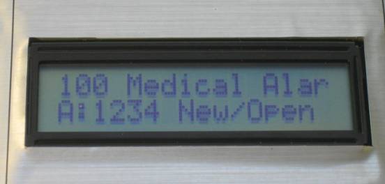
6.
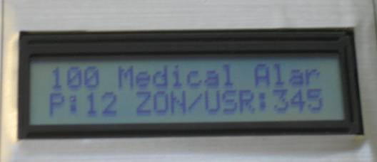
As a factory
default condition, content of alarm messages are decoded to show “131
Perimeter-Bu” on the first line and “A:1234 New/Open” or “P:01 Zon/USR:015” on
the second line to show that the event code of the alarm message was 131
Perimeter-Bu(rgular), account:1234, New message, Partition:01and Zone:015.
The following procedure requires an alarm panel. Please
follow the procedures below:
1. Connect AC/DC adapter to correct AC power. Connect the power cable to
LS15-E+/BD. Turn on the power switch on LS15-E+/BD front panel.
2. Connect provided interface cable with 9-pin D-sub connectors to PC and
LS15-E+/BD.
3. Attach an alarm panel with telephone cable at line 1 of LS15-E+/BD.
4. Change communication port number in “comport.txt”
5. Run LS15EBD.exe from Window
6. click “show alarm message”.
7. Start alarm reporting process at the alarm panel.
8. The dialed telephone number is shown in the display.
9. Alarm message is shown in the LCD display in LS15-E+/BD and also in the
edit window “status display window” on the PC screen
First-time
operation with PBX line and alarm panel
The following procedure requires an alarm panel and PBX
inside line. Please follow the procedures below:
1. Connect AC/DC adapter to correct AC power. Connect the power cable to
LS15-E+/BD. Turn on the power switch on LS15-E+/BD front panel.
2. Connect provided interface cable with 9-pin D-sub connectors to PC and
LS15-E+/BD.
3. Attach a telephone cable at line 2 of LS15-E/BD to PBX inside line.
4. Program an alarm
panel to dial PBX inside line where LS15-E+ is connected to.
5. Alarm message is
displayed on PC screen.
Alarm Receiver Software, LS15ES0.EXE:
The alarm receiver software, LS15ES0.EXE, is Windows-type.
Copy all files on a floppy disk to a new directory
“LS15E+/BD” in hard disk. Using a text editor to change communication port
number in a file “commport” if it is different.
The LS15E+/BD power must be on and the interface cable that
is provided must be connected between PC and LS15E+/BD. Then execute
LS15ES0.EXE in a hard disk
directory.
The screen displays liability question, and enter ‘y’ if
you agree with it. Exit the program and reenter the program. If everything is
set up correctly, screen should say ‘ready’. A text file, “al” is created by the alarm
receiver software. LS15EP.EXE is
MSDOS-based control program to change properties of LS15E+/BD.
Example of PC display and data stored in a file, “al”.
Alarm message number: 12354
Fri Mar 23 10:47:10 2007
Alarm message: 1234181131010158
Acount number: 1234
Event qualifier: New Event
Event code: 131 Perimeter-Burglar
Alarm
User/Zone Number: Zone 015
Partition number: 01
Date and time
and consecutive alarm message number, and stores decoded messages are stored in a text file.
The file “commport” contains communication port number as
“COM1”. If your RS232 port is other than com1, the file commport must be edited
by using a text editor.
The file “al” contains all decoded messages. When an alarm
message is received, the software opens the file “al” and stores the message
and closes the file.
Micro Seven, Inc. ®
1095-K N.E. 25th
Hillsboro, OR, U.S.A.
phone: 503-693-6982
fax: 503-693-9742
Home Page: www.microseveninc.com
Email: sales@microseveninc.com
Other
alarm receivers and related products