NEW-Stand-alone
alarm panel tester/stand-alone alarm receiver without pc and with TELEPHONE
LINE SIMULATOR function, model IP107 for contact-id, pulse 4+2 and sia format
Micro Seven, Inc. ®, models IP107 contains Alarm-Receiver/Simulator
WITH INTERNAL LCD DISPLAYS FOR DISPLAYING RECEIVED alarm messages for Ademco
contact-id, PULSE 4+2 AND SIA FORMAT. IT ALSO CONTAINS RS232 INTERFACE AND
AUDIO SPEAKER FOR HEARING ALARM REPORTING PROCESS. IP alarm receiver option is
also available.
Copyrights Micro Seven, Inc. ® 2016, 2024
Micro
Seven, Inc. model IP107 contains Alarm-Receiver Simulator and telephone line
simulator function which does not require telephone line to test and
troubleshoot alarm panels for Contact-ID, pulse 4+2 and SIA-FORMAT protocols.
The Alarm-Receiver Simulator function provides simulated telephone-line that
includes loop voltage/loop current, call progress tones, and DTMF tone receiver
for recognizing dialing by alarm panels. The simulated telephone-line functions
also include generation of dual-frequency-type call progress tones, handshake
signals for all three protocols and kissoff tones.
\
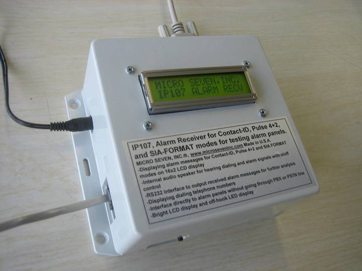
Figure 1 Picture of MICRO SEVEN-Model
IP107
Features of IP107
i
Testing of Contact-ID, Pulse 4+2, and SIA-format based alarm panels
i
International AC/DC power adapter option is available as an option
i
Handshake and kiss-off tones
i
DTMF or Rotary Pulse Dialing Input
i
Displaying raw or decoded digital alarm messages and dialed telephone numbers
on built-in 16x2 LCD display
i
Dual Frequency-type call progress tones for dial tone and ring-back tone
i
Optional RS232C interface to transmit alarm messages to PC
i
Checksum calculation of received alarm messages
i
Alarm-receiver simulator
i 4+2
protocol format
i
SIA-FORMAT
i
Internal audio speaker to hear all process and message and external
push-button to disable/enable audio speaker
i
Optional IP message receivers from Internet/Ethernet
Application and benefit
of alarm receiver
i
Demonstration and testing alarm control panels
i No
alarm receivers and no telephone lines required for testing alarm control
panels
i
Complete testing of alarm panels before the installation
i
Verifying dialing telephone numbers and digital alarm messages before
installations
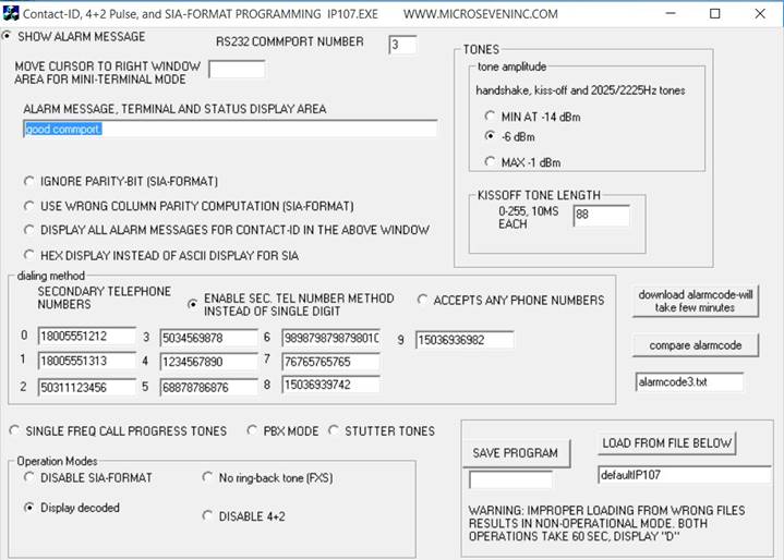
Software
IP107PROG.exe with screen display shown below for programming
telephone line simulator functions including telephone number, call progress
tones, stutter tone, and PBX mode, and loading/saving programmed data
Operation of
alarm-receivers
Traditionally,
when alarm panels are tested in the manufacturing, an alarm receiver with
telephone lines is required. The Micro Seven model IP107 provides both
simulated telephone lines and alarm receiver in a box so that your alarm panels
are connected directly to IP107.
Connect
your alarm panel to the RJ11 connector of IP107 with a regular telephone cable.
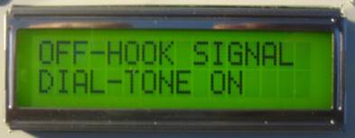
Create an event at your alarm panel to report alarm condition. When your alarm
panel goes off-hook, “OFF-HOOK SIGNAL” and “DIAL-TONE ON” are displayed on LCD
displayed on IP107. Throughout testing, all received and transmitted signals
are heard from audio speaker as factory default. It may be turned off by
pushing a push-button switch on IP107.
A
red LED on side of IP107 is turned on when telephone line input goes off-hook.
Note: actual display area is 1”(2.5cm)x2.75”(7 cm).
OFF-HOOK SIGNAL
DIAL-TONE ON
When
the alarm panel is dialing a telephone number such as a toll-free 1800-555-1212
for your alarm panel, “DIALING” and “18005551212” is shown on the LCD display.
IP107 accepts any telephone number for alarm receiver function unlike correct
telephone numbers are required to be dialed at a line when the line is
programmed as a telephone line simulator not as an alarm receiver. Since the
alarm receiver is internal, there is no ring signal generated.
Since
the alarm receiver is internal, there is no ring signal generated.
DIALING
18005551212
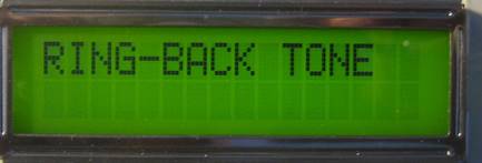
IP107
waits one second at the end of dialing process. Then it generates ring-back
tone at the line displaying “RING-BACK TONE” on the LCD display. There are two
ring-back tone periods.
IP107
waits one second at the end IP107 waits one second at the end of dialing
process. Then it generates ring-back tone at the line displaying “RING-BACK
TONE” on the LCD display. There are two ring-back tone periods.
RING-BACK TONE
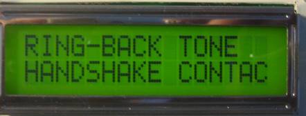
Then
IP107 generates the handshake tones with 1400 and 2300 Hz displaying “HANDSHAKE
TONES” on the LCD display.
RING-BACK TONE
HANDSHAKE TONES
Then
your alarm panel transmits sixteen-digit digital alarm message to IP107.
There
are two displaying modes. One mode displays raw sixteen-digit alarm messages on
the LCD display. The other mode displays decoded alarm messages including alarm
code, description of alarm code, account number, new/restaural/status,
zone, and partition number.
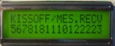
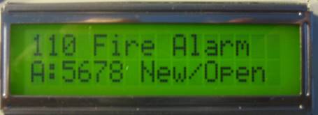
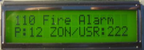
The
raw message mode displays “KISS OFF/MESS.RECV” and “567818111012223” on LCD
display. If it is the decode message mode, the display is “110 Fire Alarm” and
“A:5678 New/Open”. Where 5678 is account number and the “New/Open” is the type
of message. The display may also be either “Rest/Clos” for 3=New Restore or Closing/or “ or
Status Rp” for 6=previously-reported condition still present (Status
report).
Note:
Selection of decoded message or raw message mode is done by IP107PROG.exe. The
factory default is decoded message mode.
KISS OFF/MESS.RECV
5678181110122223
or
110 Fire Alarm
A:5678 New/Open
The
bottom portion of the display is then changed to :
“P:12 ZON/USR:222” which indicates the partition=12 and the zone=222. The
bottom portion of the display changes for every second between the account
number with type of message and partition with zone numbers. Twelve maximum
characters for each event code is displayed at 16x2 LCD module.
110 Fire Alarm
P:12 ZON/USR:222
Maximum
twelve characters are only displayed on the above LCD display for a decoded
event code.
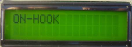
If
there was no alarm message received and IP107 goes on hook, it display “ON-HOOK” shown as below.
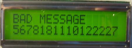
If
the checksum in the alarm message is wrong, the “BAD MESSAGE" is shown as
below with the received message.
Specifications for
alarm receiver function for Contact-ID mode:
Dialing
into alarm receiver: It accepts any numbers of any DTMF digit
when any telephone number mode is enabled or by the factory default condition,
but the maximum pause time between digits should be less than one seconds. The
maximum dialing digit is sixteen. Dialed numbers are shown in the LCD display.
Alarm
message detection signal power:
-13 dBm to +5 dBm per a frequency with maximum 4 dB different
between frequencies at the RJ11-C connector
Handshake
tones for Contact-ID mode:
1400: 1400+/- 1Hz, -20 dBm nominal power, -30 dBm power in the
line impairment mode, duration of 100 ms +/- 1.5 ms.
2300Hz: 2300+/-2 Hz, -20 dBm nominal power, -30 dBm power in the line
impairment mode, duration of 100 ms +/- 1.5 ms
Note:
Tone amplitude of handshake and kiss-off tones are programmable using the
programming software.
Handshake
tones for Pulse 4+2 mode:
1400+/- 1Hz, -20 dBm nominal power, -30 dBm power in the line
impairment mode, duration of 100 ms +/- 1.5 ms.
Kiss-off tones:
1400 +/- 1 Hz –20 dBm nominal power, -30 dBm power in the line impairment
mode with duration of 750 ms
Handshake tones for SIA-FORMAT:
2225Hz: -20 dBm nominal power, -30 dBm power in the line
impairment mode
Kiss-off tones for SIA-FORMAT
(Acknowledge tone):
2025 (positive) or 2225 (negative), -20 dBm nominal power, -30 dBm power
in the line impairment mode
Alarm
message baud-rate for SIA-FORMAT:
300 baud
Alarm
receiver software: Window-based software is provided with
IP107 for further decoding alarm messages with date/time information. Also, all
received alarm messages are stored in a disk file as continuous file. The
software may be able to transmit emails into Internet when alarm messages are
received at PC. All communications via PC are done at RS232 interface.
Control
software that is provided: IP107PROG.exe for the following:
Selection of LCD display modes between raw alarm message and
decoded alarm message
Reference: Digital Communication Standard-SIA DC-05-1999.09, Ademco Contact ID Protocol for Alarm System Communications
Limitation
of decoded information for each event: The maximum sixteen characters for each
event code is displayed on the LCD display in IP107, i.e. “101 Personal EM” or
“102 Fail-to-report” is only displayed on the LCD display because of limited
display area. Consult Micro Seven for programming your own display. Decoded
messages for the Contact-ID alarm code may be edited by using Notepad editor,
and they may be downloaded to IP107 for
Alarm
message length register with EEROM address FD:
hexadecimal 10 for Contact-ID for decimal 16, input command “MFD10” at RS232
interface using Hyper-terminal.
RS232
interface, 115200 baud, eight bit data, no parity, and
one stop bit format for outputting received alarm messages in real time.
LCD
display of 2-line of sixteen characters:
Display on-hook, off-hook status, dialing
indicator, dialed telephone number, call-progress tone indication (dial-tone,
ring-back tone, and busy tone)
Battery-feed
voltage (loop voltage): (same as the telephone line simulator
function): -20 volts:
Off-hook
impedance requirement: 400 ohms maximum DC, 600 ohms nominal AC
(same as the telephone line simulator function)
Call
Progress Tones: (same as the telephone line simulator
function)
Standard dual-frequency call progress tones, nominal -16 dBm.
Dial Tone: 350 Hz + 440 Hz, continuous unless programmed for stutter dial tone
Ring-back Tone: 440 Hz + 480 Hz, 2 sec ON/4 sec OFF.
Busy Tone: 480 Hz + 620 Hz, 0.5 sec ON/0.5 sec OFF.
Secondary
Call Progress Tones: Single-frequency tone of 480 Hz
The selection between dual frequency call frequency and single frequency type
is done by control software.
Stutter dial tone: The stutter dial tone with three of
0.1 seconds on/off period following with continuous dial tone.
Simulated PBX Mode:
The simulated PBX mode where dial tone returns after dialing 9:
Accepts Any Phone Numbers: Any phone numbers are accepted except in
the Simulated PBX Mode. Dialing any phone number with “2” in the beginning
returns ring-back tone immediately.
Line characteristics: (same as the telephone line simulator function)
Input impedance at 1 k Hz: 600 ohms +/- 5%
Line Input Jacks: USOC-RJ11-C, standard modular phone jack (same as the
telephone line simulator function) located on rear panel
Switch: Audio speaker enable/disable, setting is restored upon power recycled
Calibration:
not required because digitally synthesized tones
Power Requirements:
24VDC power input by
provided 117VAC/24VDC power adapter
Dimensions:
5”x5”x3”.
Line Status Display: red LED to indicate off-hook status
Power On Indicator:
green LED display, flashing
Weight:
1 lbs. (1 kg.)
Environmental:
Operating temperature: 0 to 35 degree C, Humidity: 85% RH at 35 degree C
Warranty/Service: 6
months limited warranty. No warranty if any factory seal is broken. Service is
performed at the factory, usually within 5 working days.
4+2
protocol features:
SIA Pulse Format P3 in SIA DC-02-1992.02 (R2000.05), section 4.1.3
Pulse Format P3 is provided.
Note: IP107 generates kissoff tone for 4+2 mode
first. If there is no 4+2 communication for four seconds, contact-ID handshake
is generated.
Four digits for account number, one digit for event, and last digit for zone.
One period consists of 1900 Hz on for 25ms and tone-off for 25ms.
Handshake signal: 1400Hz tone for one second long.
Kiss-off tone: 1400Hz tone for one second long.
Double transmission is required for generating kissoff
tone.
Event codes that are supported and are decoded for LCD display:
01,02,03, 04 --- 09 personal emergency, 2 way voice –zones 1 through 9
40 - AC loss
50 – Restoral AC Loss
61-69, loss of supervision, zones 1-9
71-79, restoral –loss of radio supervision
41-49, low battery with zones 1 –9
51-59, restoral low battery with zones 1-9
30, test report
Note: similar decoded message display in Pulse 4+2 mode is also provided.
Options:
1.
International AC/DC Power Adapter Option
for 90-250VAC, 50/60Hz
2.
Less expensive model IP107-1 without
SIA-FORMAT
3.
IP alarm receiver from Internet/Ethernet,
which outputs received DC09-type IP messages at RS232 interface. See more
details in http://www.microseveninc.com/brocher15a.htm
IP107-IP-option
Received DC-09 type messages are displayed in LCD panel as one of
the following four display formats which is programmed by using IPPROG7.exe.
1.
Raw format mode
Because received IP messages contains more
than 32 characters, two or more screens are displayed consecutively.
2.
Sugart
format mode where 4429 is an account number, E for a new message, 601 for an
event code, 01 for partition, and 250 is zone.
Example: 5112 184429E60101250
3.
Decoded format mode
Contact-ID message for telephone is
constructed from received DC09 message.
Example: 4429181601011250
4.
Decoded format mode 2
Example: #4429 N P01 Z250
601 Manual Trig
Where 4429 is an account number, N for a new message, P01 for a
partition 01,
Z250 for zone 250,
601 for event code for Manual Trigger.
Micro Seven, Inc. ®
Home Page: www.microseveninc.com
Email: sales@microseveninc.com
Other
alarm receivers and related products