MICRO
SEVEN System Configuration, ATS1000, Alarm Test System monitors incoming alarm
signals and transmitting alarm signals at remote alarm panels, test central
station telephone lines and alarm receivers
COPYRIGHTS MICRO SEVEN, INC. 2017
Alarm Test System, ATS1000
Objectives:
Verification of Contact-ID alarm signal reception at central
station
Testing of central station telephone lines and central
station alarm receiver
Verification of remote alarm panel transmission
System components:
Central station incoming alarm signal monitor, IP105C
Remote alarm signal monitor, IP105R for each remote panel
Test telephone line dialer, AP15-2
IP receiver, ER15A
CENTRALIP_V2.EXE
AP15DEMO2a+.exe
Features:
No
affects in existing alarm panel operation and central station receiver
Reading
of transmitted Contact-ID messages at remote installation
Reading
of transmitted Contact-ID messages at central station
Testing
central station telephone lines and alarm receiver operation
History
file generation inside IP105 Alarm Monitor
Figure1
reading alarm messages at remote panel and central station in ATS1000
IP105R Alarm Remote
Monitor outputs DC09 IP message to ER15A IP Receiver over
Internet/Ethernet by reading Contact-ID messages over telephone line at remote
alarm panel. If there is no Internet available, the received alarm messages are
stored in EEROM inside the alarm monitor. Also at the same time, IP105C Alarm
Central Monitor reads the exact Contact-ID alarm message that was sent to the
central monitoring station at the telephone line and outputs DC09 IP message to
ER15A IP Receiver over Internet/Ethernet. The IP message may includes data in
the original Contact-ID alarm message with remote or central alarm monitor. An
application program, CENTRALIP_V2.EXE displays and stores received alarm
messages in PC via RS232 interface. IP105 may be brought back to a shop for
reading history data in EEROM. Also note that ER15A can be selected to generate
Sur-Gard MLR2E formatted string instead of decoded alarm messages at RS232
interface.
In
order to test central station telephone lines and alarm receiver, AP15-2, PC Alarm Panel is
used. ATS1000 app includes automatic telephone dialing and transmitting test
messages. Test messages are transmitted continuously in 24/7 timing to your
existing central station alarm receiver at any interval. Any problem or failed
operation is reported as an email or as a text message. The auto dialer portion
of ATS1000 app is shown below:
The screen shot
of AP15DEMO2a.exe is shown above. Twenty central station telephone numbers are
tested. Failed telephone line after trying three dialing attempts. After a
number of successful tests, an email is also generated.
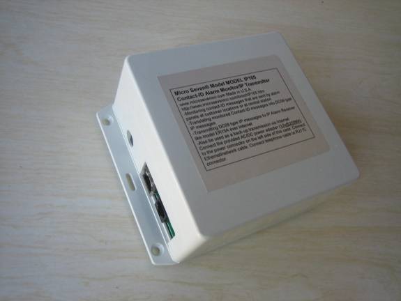
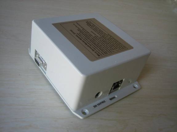
IP105 is
shown in the above picture. IP105 box contains Internet/Ethernet connector,
telephone jack, power connector, and power indicator. AC/DC power adapter is
also included as a standard accessory.
ER15A is
shown in the above picture. ER15A contains Internet/Ethernet connector, RS232 connector,
power connector and power indicator. AC/DC power adapter is also included as a
standard accessory.
Micro Seven, Inc. ®
1095-K N.E. 25th Ave.
Hillsboro, OR
97124 U.S.A.
phone:
503-693-6982, fax: 503-693-9742